Engineering-Grade LiDAR Scanning

They Donโ€™t Just Scan โ€” They Take Responsibility

Engineering-grade LiDAR scanning is not about collecting point clouds.
It is about taking responsibility for the data that engineering, fabrication, and shutdown decisions are made from.

At Hamilton By Design, engineering-grade LiDAR scanning means the scan is:

  • Planned by engineers
  • Verified by engineers
  • Used directly for design and fabrication
  • Owned by engineers when it matters

If a scan cannot be confidently designed from, fabricated from, and installed from, it is not engineering grade.


โ€œWeโ€™ve seen too many projects fail because everyone assumed the scan was โ€˜good enoughโ€™.
At Hamilton By Design, we donโ€™t just deliver LiDAR data โ€” we take responsibility for whether it can actually be designed and built from.
If weโ€™re involved, someone owns the outcome.โ€

โ€” General Manager, Hamilton By Design


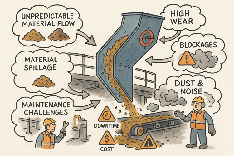
Why Most LiDAR Scans Fail Engineering Projects

We regularly encounter projects where:

  • โ€œWe trusted the data and got burned.โ€
  • โ€œThe drawings didnโ€™t match reality.โ€
  • โ€œNo one wanted to own it when it went wrong.โ€

In most cases, the issue isnโ€™t the scanner.

The issue is that the scan was treated as a data product, not an engineering input.

Scan-only services deliver point clouds.
Engineering-grade LiDAR delivers confidence, accountability, and defensible outcomes.


What Makes LiDAR โ€œEngineering-Gradeโ€

Engineering-grade LiDAR scanning is defined by how the scan is controlled, interpreted, and used, not by scan density or marketing claims.

1. Engineering-Led Scan Planning

Before scanning begins, engineers define:

  • What must fit together
  • What tolerances actually matter
  • What will be fabricated, replaced, or installed
  • Where shutdown or safety risk exists

This ensures the scan is fit-for-purpose, not just visually impressive.


2. Accuracy Is Verified โ€” Not Assumed

Engineering-grade scanning includes:

  • Controlled scan resolution and overlap
  • Registration reviewed using engineering judgement
  • Scale and geometry checked against known site features
  • Accuracy assessed relative to design intent

A dense point cloud does not guarantee engineering reliability.


3. Engineering Interpretation of Brownfield Reality

Real industrial assets are rarely perfect. They are:

  • Worn
  • Modified
  • Repaired
  • Out of square

Engineering-grade LiDAR scanning includes:

  • Interpretation of deformation and wear
  • Identification of unreliable geometry
  • Clear documentation of assumptions and exclusions

This is where engineering experience prevents downstream rework.


4. Data That Works Directly in CAD & Fabrication

Engineering-grade LiDAR data is:

  • Structured for SolidWorks and Inventor
  • Used directly for fabrication-ready models and drawings
  • Suitable for interference checks and constructability reviews

If a scan cannot be confidently used in CAD, it is not engineering-grade.

Point Clouds – 3D Scans – Engineering Quality – Past Projects


  • 3D LiDAR point cloud of an industrial plant structure

5. Ownership When It Matters Most

Engineering-grade LiDAR scanning means:

  • One party owns the scan-to-design interface
  • Assumptions are explicit and traceable
  • Engineering judgement is applied โ€” not avoided

This is critical when:

  • Shutdown windows are tight
  • Fabrication is off-site
  • Parts must fit together first time
  • Designs must be defensible in audits or reviews

Our clients:


Why Fabricators and Shutdown Teams Value This Approach

Engineering-grade LiDAR scanning enables:

  • Seamless delivery where parts fit together
  • Reduced RFIs and site rework
  • Predictable shutdown execution
  • Fit-first-time fabrication

We design with fabrication and installation in mind, because that is where projects succeed โ€” or fail.


Where Engineering-Grade LiDAR Is Essential

  • Mining and minerals processing facilities
  • Power generation and utilities
  • Manufacturing and process plants
  • Brownfield upgrades and tie-ins
  • Shutdown-critical replacement works
  • Reverse engineering of undocumented assets
  • Safety-critical access platforms and structures

Hamilton By Design logo displayed on a blue tilted rectangle with a grey gradient background

Engineering-Grade LiDAR Is Risk Management

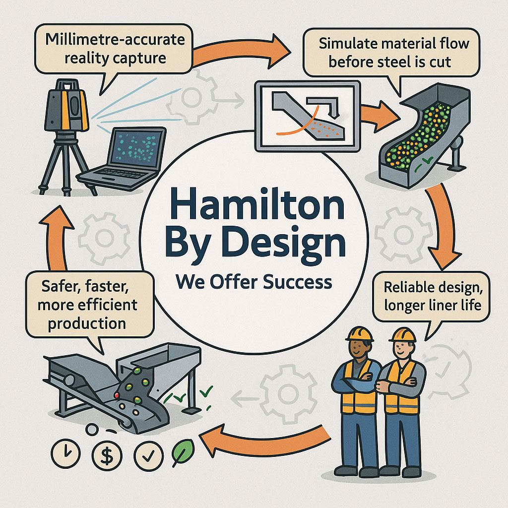
At Hamilton By Design, LiDAR scanning is not sold as a standalone service.

It is part of an engineering-led delivery model that connects:

  • Reality capture
  • Mechanical and structural design
  • Fabrication documentation
  • Installation confidence

We do not compete on lowest scan cost.
We compete on ownership, accountability, and outcome.


Detailing Transfer Stations in the Age of Digital Engineering

Transfer stations and chutes sit at the intersection of bulk materials handling, structural engineering, and fabrication practicality. While the fundamentals of good detailing have not changed, the way engineers now capture, coordinate, and validate these details has evolved significantly over the past decade.

This article revisits the principles of transfer station detailing and places them in a modern digital-engineering context, where accurate site data, constructability, and lifecycle performance are critical.


Engineering illustration of a transfer chute showing a LiDAR point cloud overlay aligned with the same chute geometry for as-built verification.

Why Transfer Station Detailing Still Matters

Poorly detailed transfer stations remain one of the most common sources of:

  • Material spillage and dust generation
  • Accelerated liner and structure wear
  • Unplanned downtime and maintenance escalation
  • Safety risks to operators and maintainers

In many cases, the root cause is not the concept design, but inadequate detailing and incomplete understanding of site geometry.

Even well-intended designs can fail if:

  • Existing structures are misrepresented
  • Conveyor interfaces are assumed rather than measured
  • Fabrication tolerances are not realistically achievable on site

The Shift from Assumed Geometry to Measured Reality

Historically, detailing relied heavily on:

  • Legacy drawings
  • Manual tape measurements
  • Partial site surveys
  • โ€œBest guessโ€ alignment assumptions

Today, engineering-grade reality capture has fundamentally changed what is possible.

Using 3D laser scanning (LiDAR), engineers can now work from:

  • Millimetre-accurate point clouds
  • Verified conveyor centre lines
  • True chute-to-structure interfaces
  • Real as-installed conditions rather than design intent

This shift dramatically reduces site rework and fabrication clashes.

This approach is central to how Hamilton By Design supports bulk materials handling upgrades across mining, ports, and heavy industry.


Detailing Considerations That Still Get Missed

Even with modern tools, certain detailing fundamentals remain critical.

1. Interface Accuracy

Transfer stations often interface with:

  • Existing conveyors
  • Walkways and access platforms
  • Structural steelwork installed decades earlier

Without accurate as-built data, small errors compound quickly. Laser scanning eliminates this uncertainty.

Related reading:
https://www.hamiltonbydesign.com.au/3d-laser-scanning-engineering/


2. Wear Liner Integration

Good detailing must account for:

  • Liner thickness variation
  • Fixing access and replacement paths
  • Load paths through liners into structure

Digitally modelling liners within the chute geometry allows engineers to validate:

  • Clearances
  • Installation sequence
  • Maintenance access before steel is cut

3. Fabrication Reality

A detail that looks acceptable in 2D can become problematic when fabricated.

Modern workflows now link:

  • 3D scanning
  • Solid modelling
  • Fabrication drawings
  • Digital QA checks

This reduces site modifications and ensures components fit first time.

Example of fabrication-ready workflows:
https://www.hamiltonbydesign.com.au/mechanical-engineering-design-services/


Transfer Stations as Systems, Not Isolated Chutes

A key lesson reinforced over time is that transfer stations must be treated as systems, not standalone components.

Good detailing considers:

  • Upstream and downstream belt tracking
  • Material trajectory consistency
  • Structural vibration and dynamic loading
  • Maintenance access under real operating conditions

Digital engineering allows these interactions to be reviewed early, reducing operational risk.


The Role of Engineering-Led Scanning

Not all scans are equal.

For engineering applications, scanning must be:

  • Performed with known accuracy
  • Registered and verified correctly
  • Interpreted by engineers, not just technicians

This distinction matters when designs are used for fabrication and compliance.

Hamilton By Designโ€™s approach combines engineering-led LiDAR scanning with mechanical design, ensuring the data collected is suitable for real engineering decisions.

Learn more:
https://www.hamiltonbydesign.com.au/engineering-led-3d-lidar-scanning/


Closing Thoughts

While detailing principles for transfer stations have stood the test of time, the tools and expectations have changed.

Modern projects demand:

  • Verified geometry
  • Fabrication-ready models
  • Reduced site risk
  • Higher confidence before steel is ordered

By integrating reality capture, detailed modelling, and constructability thinking, transfer station detailing can move from a risk point to a performance advantage.


Hamilton By Design logo displayed on a blue tilted rectangle with a grey gradient background

Our clients:


Name
Would you like us to arrange a phone consultation for you?
Address

Further Reading

3D Scanning & Engineering in Hervey Bay

Hervey Bayโ€™s Coastal Advantage: How 3D LiDAR Scanning, Engineering & Digital Modelling Are Powering Smarter Regional Projects

Hervey Bay is known worldwide for its calm waters, iconic whale encounters and its role as the gateway to Kโ€™gari (Fraser Island). But behind the postcard coastline lies a fast-growing regional city with expanding infrastructure, marine industries, coastal engineering needs and ongoing urban development. As Hervey Bay continues to grow, so does its need for accurate mapping, reliable engineering and smarter digital-based project delivery.

Hamilton By Design is proud to support the region with 3D LiDAR laser scanning, mechanical and structural engineering services, 3D modelling and CAD drafting โ€” tools that help reduce construction risk, improve upgrade planning, support marine and coastal infrastructure, and streamline fabrication and installation.

Whether you’re upgrading a jetty, renovating a foreshore asset, documenting a marina, expanding a workshop or designing new coastal facilities, our digital engineering approach ensures precision and confidence from the very beginning.


Why Hervey Bay Is a Unique Environment for Engineering & 3D Scanning

Hervey Bay stands apart from other Queensland cities because of its geographical protection, marine behaviour, ecological sensitivity and coastal development patterns. These unique conditions make accurate spatial data and robust engineering essential.

Hereโ€™s what sets the region apart:

1. Calm, Protected Waters Created by Kโ€™gari (Fraser Island)

Hervey Bay sits behind the worldโ€™s largest sand island, which shields the city from ocean swell. This rare geographic feature enables:

  • ideal boating and marine-access conditions
  • predictable marine construction windows
  • lower wave stress on coastal structures
  • consistent eco-tourism operations

Few places on earth have this natural barrier, making precise coastal modelling essential for designing long-life marine assets.

2. World-Famous Whale Nursery

Hervey Bay is the worldโ€™s first Whale Heritage Site, known for the behaviour of humpback whales who stop here with their calves.

Environmental sensitivity means many projects require:

  • accurate as-built documentation
  • ecological planning
  • digital modelling to minimise impacts
  • detailed engineering reports for compliance

3. Rapid Coastal Development and Urban Expansion

The region is one of Queenslandโ€™s fastest-growing coastal centres. New marinas, foreshore upgrades, residential developments and tourism infrastructure require accurate ground modelling and precise design.

4. A Strong Marine, Fabrication & Light-Industrial Sector

Slipways, fabrication yards, marine workshops and coastal civil contractors all depend on precise measurements and accurate drafting to minimise rework.

This mix of marine, civil and light-industry projects is exactly why 3D LiDAR scanning and digital engineering matter in Hervey Bay.


3D LiDAR Laser Scanning โ€” The Foundation of Accurate Coastal & Industrial Projects

Coastal infrastructure often includes complex geometry, ageing assets, variable terrain and environmental constraints that make traditional surveying slow and unreliable. Thatโ€™s where 3D LiDAR scanning becomes a game-changer.

Hamilton By Design provides high-accuracy scanning that captures:

  • marinas, jetties, pontoons and foreshore structures
  • workshops, fabrication sheds and industrial sites
  • terrain, drainage channels and coastal slopes
  • mechanical equipment, platforms and walkways
  • existing buildings for upgrades or conversions
  • complex pipework, tanks and utility lines

The result is a millimetre-accurate digital representation of your site โ€” a data-rich foundation for design, clash detection, feasibility studies and fabrication planning.

Learn more about scanning capabilities here:
3D Laser Scanning

For Hervey Bay clients, this means:

  • fewer site visits
  • faster design turnaround
  • improved coordination between contractors
  • reduced rework and installation errors
  • clearer visualisation for approvals and planning

In a region where weather, tides and tourism windows matter, efficient and accurate design matters even more.


3D Modelling & Drafting โ€” Turning Point Clouds into Build-Ready Designs

Once your site is scanned, Hamilton By Design transforms the data into full 3D CAD models and fabrication-ready drawings. This is essential for:

  • marine structures and coastal engineering
  • industrial and fabrication workshops
  • building upgrades or repurposing
  • mechanical equipment layout and installation
  • compliance and safety documentation

We deliver:

  • structural steel models
  • mechanical assemblies
  • GA and detail drawings
  • pipework and flow system layouts
  • workshop fit-outs
  • clash detection and interference checks
  • complete drawing packages with BOMs

In Hervey Bay, where many facilities evolve in stages over time โ€” marinas, boating facilities, industrial sheds, tourist infrastructure โ€” having an accurate digital model avoids expensive mistakes.


Engineering Services Tailored to Hervey Bayโ€™s Coastal & Industrial Landscape

Hervey Bayโ€™s engineering needs are shaped by:

  • coastal exposure
  • saltwater corrosion
  • tidal influences
  • marine loading
  • environmental sensitivity
  • ageing civil assets
  • strong fabrication and workshop activity

Hamilton By Design supports these needs with comprehensive mechanical and structural engineering including:

Mechanical Engineering

  • equipment layout and optimisation
  • marine-grade design modifications
  • conveyor, pump, motor and mechanical upgrades
  • fatigue and stress analysis
  • flow and process improvements

Structural Engineering

  • wharf and jetty modifications
  • platform and walkway design
  • structural integrity assessments
  • corrosion management & replacement design
  • footings, mounting and support structures
  • upgrades for load, access or compliance

Every project is grounded in real, verified site data, delivered through laser scanning.


Where Our Services Add the Most Value in Hervey Bay

1. Foreshore, Marina & Coastal Infrastructure Upgrades

Scanning provides exact geometry for:

  • seawalls
  • boardwalks
  • jetties
  • pontoons
  • boat ramps
  • retaining structures
  • marine-service assets

2. Workshop, Fabrication & Light-Industrial Facilities

Accurate capture of existing layouts helps:

  • optimise machinery placement
  • design new steelwork
  • eliminate fit-up errors
  • streamline fabrication

3. Tourism & Eco-Experience Infrastructure

Projects near sensitive environmental zones benefit from:

  • low-impact, non-intrusive scanning
  • terrain modelling
  • digital planning documentation

4. Council & Civil Infrastructure

LiDAR supports:

  • drainage upgrades
  • road and footpath modelling
  • structural assessments
  • coastal resilience planning

5. Building Renovations & Commercial Upgrades

Perfect for:

  • repurposed spaces
  • cafes, tourism centres, warehouses
  • multi-stage redevelopment projects

End-to-End Workflow for Bundaberg Projects

Hamilton By Design delivers a fully integrated service:

  1. 3D LiDAR scanning
  2. Point-cloud processing & accuracy verification
  3. 3D CAD modelling
  4. Mechanical & structural engineering
  5. Fabrication-ready drawings
  6. Digital QA & documentation

Thereโ€™s one team, one workflow and one level of accountability โ€” reducing delays, confusion and rework.


Hamilton By Design logo displayed on a blue tilted rectangle with a grey gradient background

Hervey Bayโ€™s Future Is Digital โ€” And Hamilton By Design Is Ready

Hervey Bay is transforming. With coastal development, marina upgrades, eco-tourism expansion, workshop growth and rising residential infrastructure, the region needs accurate, digital, engineering-grade solutions more than ever.

Hamilton By Design is here to provide:

  • precision 3D LiDAR scanning
  • engineering for marine, civil and industrial facilities
  • 3D modelling and drafting
  • digital quality assurance
  • fabrication-ready deliverables

Whether you’re planning a new coastal asset, redesigning a workshop, improving a facility or upgrading existing infrastructure, our team ensures accuracy, safety and efficiency every step of the way.


Our Clients

Name
Would you like us to arrange a phone consultation for you?
Address

Chute Design in the Mining Industry

Infographic showing Hamilton By Designโ€™s engineering workflow, including millimetre-accurate LiDAR reality capture, material-flow simulation, optimised chute designs, and safer, more efficient production outcomes. Two workers in PPE highlight reliable design and longer liner life, with icons representing time, cost and quality benefits.

Getting Coal, Hard Rock, and ROM Material Flow Right

Chute design is one of the most critical yet challenging aspects of mining and mineral processing. Whether you are handling coal, hard rock ore, or raw ROM material, chutes and transfer stations are the unsung workhorses of every operation. When designed well, they guide material smoothly, minimise wear, and keep conveyors running. When designed poorly, they cause blockages, spillage, excessive dust, and expensive downtime.

Modern chute design has moved far beyond rules of thumb and back-of-the-envelope sketches. Today, successful projects rely on accurate as-built data, particle trajectory analysis, and advanced Discrete Element Method (DEM) simulation to predict, visualise, and optimise material flow before steel is cut. In this article, we explore why these tools have become essential, how they work together, and where software can โ€” and cannot โ€” replace engineering judgement.


Illustration showing common problems with poorly designed material-handling chutes. A chute discharges material onto a conveyor while issues are highlighted around it: unpredictable material flow, material spillage, maintenance challenges, high wear, blockages, and dust and noise. Warning icons for downtime and cost appear on the conveyor, and workers are shown dealing with the resulting hazards and maintenance tasks.

The Challenge of Chute Design

Coal and hard rock have very different flow behaviours. Coal tends to be softer, generate more dust, and be prone to degradation, while hard rock is more abrasive and can damage chutes if impact angles are not controlled. ROM material adds another level of complexity โ€” oversize lumps, fines, and moisture variation can cause hang-ups or uneven flow.

Chute design must balance several competing objectives:

  • Control the trajectory of incoming material to reduce impact and wear
  • Prevent blockages by maintaining flowability, even with wet or sticky ore
  • Manage dust and noise to meet environmental and workplace health requirements
  • Fit within existing plant space with minimal modification to conveyors and structures
  • Be maintainable โ€” liners must be accessible and replaceable without excessive downtime

Meeting all these goals without accurate data and simulation is like trying to design in the dark.


Illustrated graphic showing a tripod-mounted 3D laser scanner capturing millimetre-accurate as-built data in an industrial plant with conveyors and walkways. Speech bubbles highlight issues such as โ€œOutdated drawings donโ€™t tell the full storyโ€ and โ€œModifications rarely get documented.โ€ The scan data is shown being visualised on a laptop, with notes describing full coverage of conveyors, walkways, and services. Benefits listed along the bottom include faster data collection, fewer site revisits, safer shutdowns, accurate starting point for design simulation, and safer outcomes that ensure designs fit first time.

Capturing the Truth with 3D Scanning

The first step in any successful chute project is to understand the as-built environment. In many operations, drawings are outdated, modifications have been made over the years, and the real plant geometry may differ from what is on paper. Manual measurement is slow, risky, and often incomplete.

This is where 3D laser scanning changes the game. Using tripod-mounted or mobile LiDAR scanners, engineers can capture the entire transfer station, conveyors, surrounding steelwork, and services in a matter of hours. The result is a dense point cloud with millimetre accuracy that reflects the true state of the plant.

From here, the point cloud is cleaned and converted into a 3D model. This ensures the new chute design will not clash with existing structures, and that all clearances are known. It also allows maintenance teams to plan safe access for liner change-outs and other work, as the scanned model can be navigated virtually to check reach and access envelopes.


Understanding Particle Trajectory

Once the physical environment is known, the next challenge is to understand the particle trajectory โ€” the path that material takes as it leaves the head pulley or previous transfer point.

Trajectory depends on belt speed, material characteristics, and discharge angle. For coal, fine particles may spread wider than the coarse fraction, while for ROM ore, large lumps may follow a ballistic path that needs to be controlled to prevent impact damage.

Accurately modelling trajectory ensures that the material enters the chute in the right location and direction. This minimises impact forces, reducing wear on liners and avoiding the โ€œsplashโ€ that creates spillage and dust. It also prevents the material from hitting obstructions or dead zones that could lead to build-up and blockages.

Modern software can plot the trajectory curve for different loading conditions, providing a starting point for chute geometry. This is a critical step โ€” if the trajectory is wrong, the chute design will be fighting against the natural path of the material.


The Power of DEM Simulation

While trajectory gives a first approximation, real-world flow is far more complex. This is where Discrete Element Method (DEM) simulation comes into play. DEM models represent bulk material as thousands (or millions) of individual particles, each following the laws of motion and interacting with one another.

When a DEM simulation is run on a chute design:

  • You can visualise material flow in 3D, watching how particles accelerate, collide, and settle
  • Impact zones become clear, showing where liners will wear fastest
  • Areas of turbulence, dust generation, or segregation are identified
  • Build-up points and potential blockages are predicted

This allows engineers to experiment with chute geometry before fabrication. Angles can be changed, ledges removed, and flow-aiding features like hood and spoon profiles or rock-boxes optimised to achieve smooth, controlled flow.

For coal, DEM can help ensure material lands gently on the receiving belt, reducing degradation and dust. For hard rock, it can ensure that the energy of impact is directed onto replaceable wear liners rather than structural plate. For ROM ore, it can help prevent oversize lumps from wedging in critical locations.


Illustration of an optimised chute design showing material flow represented by green particles, with check marks and gear icons indicating improved efficiency and engineered performance.

๐Ÿ–ฅ Strengths and Limitations of Software

Modern DEM packages are powerful, but they are not magic. Software such as EDEM, Rocky DEM, or Altairโ€™s tools can simulate a wide range of materials and geometries, but they rely on good input data and skilled interpretation.

Key strengths include:

  • Ability to model complex, 3D geometries and particle interactions
  • High visualisation power for communicating designs to stakeholders
  • Capability to run multiple scenarios (different feed rates, moisture contents, ore types) quickly

However, there are limitations:

  • Material calibration is critical. If the particle shape, friction, and cohesion parameters are wrong, the results will not match reality.
  • Computational cost can be high โ€” detailed simulations of large chutes with millions of particles may take hours or days to run.
  • Engineering judgement is still needed. Software will not tell you the โ€œbestโ€ design โ€” it will only show how a proposed design behaves under given conditions.

Thatโ€™s why DEM is best used as part of a holistic workflow that includes field data, trajectory analysis, and experienced design review.


From Model to Real-World Results

When the simulation results are validated and optimised, the design can be finalised. The point cloud model ensures the chute will fit in the available space, and the DEM results give confidence that it will perform as intended.

This means fabrication can proceed with fewer changes and less risk. During shutdown, installation goes smoothly, because clashes have already been resolved in the digital model. Once commissioned, the chute delivers predictable flow, less spillage, and longer liner life.


Why It Matters More Than Ever

Todayโ€™s mining operations face tighter production schedules, stricter environmental compliance, and increasing cost pressures. Downtime is expensive, and the margin for error is shrinking.

By combining 3D scanning, trajectory modelling, and DEM simulation, operations can move from reactive problem-solving to proactive improvement. Instead of waiting for blockages or failures, they can design out the problems before they occur, saving both time and money.


Partnering for Success

At Hamilton by Design, we specialise in turning raw site data into actionable insights. Our team uses advanced 3D scanning to capture your transfer stations with precision, builds accurate point clouds and CAD models, and runs calibrated DEM simulations to ensure your new chute design performs from day one.

Whether youโ€™re working with coal, hard rock, or ROM ore, we help you deliver designs that fit first time, reduce maintenance headaches, and keep production running.

Contact us today to see how our integrated scanning and simulation workflow can make your next chute project safer, faster, and more reliable.

Mechanical Engineering | Structural Engineering

Mechanical Drafting | Structural Drafting

3D Laser Scanning | 3D CAD Modelling | 3D Scanning

Chute Design

SolidWorks Contractors in Australia

Hamilton By Design โ€“ Blog

Consulting Engineers

About Us โ€“ Hamilton By Design

Hamilton By Design | 3D Scanning | Sydney | Perth | Brisbane | Mount Isa | Lidar Scanning

Contact us

Are You Getting the Full Value from Your Point Cloud Data?

ย 

3D Scanning

The world of manufacturing and fabrication is moving faster than ever. Point cloud scanning and 3D modeling have made it easier to capture reality with incredible accuracy โ€” but simply collecting data isnโ€™t enough.

Without the right expertise, point clouds often sit unused, underutilized, or worse โ€” lead to costly mistakes when converted into incomplete or inaccurate drawings.

3D Scanning

ย 

ย 

Thatโ€™s why mechanical engineering consultants are becoming essential partners for forward-thinking businesses. They donโ€™t just process point clouds โ€” they turn them into:

  • High-precision 3D models that match real-world conditions

  • Fabrication-ready drawings that reduce errors and rework

  • Actionable insights that save time, money, and frustration

This is no longer just about technology โ€” itโ€™s about strategy and execution.

ย 

Read our full article to discover why now is the perfect time to engage consultants who can unlock the power of your point cloud data:


Itโ€™s Time to Level Up: Why Mechanical Engineering Consultants Are Key to Unlocking the Power of Point Cloud to 3D Modeling

ย 

ย 


Hamilton By Design logo displayed on a blue tilted rectangle with a grey gradient background

Our clients:

Name
Would you like us to arrange a phone consultation for you?
Address