3D Laser Scanning in Parramatta: Engineering-Grade Data for Safer Conveyor Systems and Better Risk Management

Watercolour illustration of engineers 3D laser scanning a warehouse conveyor system.

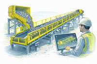
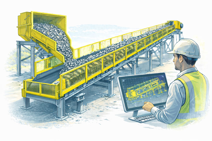
In consumer goods manufacturing, distribution centres and logistics facilities around Parramatta and Western Sydney, conveyor systems are mission-critical. Whether moving pallets, cartons, bottles, or bulk packaged goods, these systems must integrate with structural steel, mechanical equipment and building services without compromise.

Yet many existing facilities are built from legacy drawings, partial records or hand-measured surveys. This creates risk when planning upgrades, expansions or tie-ins โ€” especially where conveyors interface with mezzanines, sortation systems, robotics and utilities.

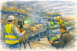
3D laser scanning provides a precise and reliable basis for understanding whatโ€™s actually on site before detailed engineering or shutdown activities begin.


Why Scan First? Engineering-Grade Reality Is the Backbone of Success

A good conveyor design solution depends on accurate understanding of:

  • where conveyors really sit in 3D space
  • how structural beams, columns and supports interact
  • exact locations of mechanical equipment
  • existing pipework, ducts and cable trays
  • access clearances for maintenance and shutdown execution

Traditional tape measures and manual field sketches are slow, error-prone and not suitable for complex conveyor networks. In contrast, 3D laser scanning captures millions of points in minutes and produces engineering-grade point clouds that reflect every surface, pipe, beam and conveyor geometry exactly as it exists.

This scan becomes the backbone of your engineering workflow โ€” a verified digital reference that informs design, reduces risk and underpins safe execution.


3D scanning of FMCG conveyor line shown in soft watercolour style.

From Reality Capture to Practical Engineering Outputs

A registered 3D point cloud delivers value throughout the project lifecycle. Typical deliverables include:

  • Full as-built point clouds: a complete digital record of existing conditions
  • Clash analysis models: identify conflicts between conveyors, structures and services
  • Fabrication-ready geometry: for skid frames, guards, support steel and pipe spools
  • DXF/STEP/Parasolid exports: for mechanical and structural drafting
  • Compatibility with Revit, AutoCAD, Navisworks: for design coordination

The result? Engineers spend more time solving real problems and less time correcting assumptions.


Designing for Safer Conveyor Integration

Upgrading or modifying conveyor systems in FMCG and logistics environments often involves:

  • adding sortation or scanning stations
  • rerouting belt paths to accommodate new equipment
  • expanding mezzanines or catwalks
  • integrating with automated storage and retrieval systems
  • adjusting utilities like compressed air, water or power services
  • installing guarding and safety infrastructure

Each of these tasks intersects with steelwork, services and building elements. Using 3D scan data for design coordination enables:

โœ” accurate spatial modelling
โœ” reduced field rework
โœ” clearer installation instructions
โœ” fewer late changes during shutdowns

This translates directly to lower cost, higher safety and greater schedule confidence.


Better Risk Management Through Verified Data

Conveyor upgrades and expansions are typically scheduled during short shutdown windows. Risk drivers commonly include:

  • uncertainty about existing conditions
  • interference with critical services
  • tight clearances that limit access
  • unexpected clashes on installation
  • insufficient documentation for permits or safety reviews

With scan-derived data, these risks are mitigated early. Design teams can model scenarios before fabrication, check for clashes electronically and articulate installation sequences with confidence.

This isnโ€™t just better practice โ€” itโ€™s good risk management.


As-Built Scanning for Handover Confidence

At project completion, a final 3D laser scan provides an accurate digital as-built model of the upgraded systems. This has several benefits:

  • avoids tape measure as-builts
  • records exact installation geometry
  • supports maintenance planning
  • provides a robust platform for future works
  • becomes an asset for ongoing risk assessments

The organisation receives not just installed equipment, but a verified digital twin for operations and design.


Applications Around Parramatta & Western Sydney

3D laser scanning is highly effective in these local industries:

โœ” FMCG production facilities
โœ” Beverage and food processing plants
โœ” Automated distribution centres
โœ” Parcel sortation hubs
โœ” Packaging and assembly lines
โœ” Warehouse conveyor networks
โœ” Industrial plant upgrades

Across these environments, conveyors are fundamental to throughput โ€” and accurate data is fundamental to success.


Hamilton By Design logo displayed on a blue tilted rectangle with a grey gradient background

3D LiDAR scanning and 3D modelling service button โ€” laser scanner capturing a point cloud for engineering and CAD modelling
Mechanical engineering services

Unlock Better Project Outcomes with 3D Scanning

A robust reality capture strategy delivers measurable improvements to:

  • safety protocols
  • design accuracy
  • fabrication efficiency
  • shutdown predictability
  • project cost control

In an industrial region like Parramatta โ€” where competitiveness depends on efficiency and certainty โ€” laser scanning is not just technology, itโ€™s a strategic engineering enabler.


Ready to Elevate Your Conveyor Project?

If youโ€™re planning a conveyor upgrade, system extension, or facility modification in the Parramatta or Western Sydney region, start with accurate reality capture.

Hamilton By Design Co. provides tailored 3D laser scanning services that support safer, more reliable, and more successful industrial outcomes.

Scan first.
Design with confidence.
Finish with a verified as-built.

Name
Would you like us to arrange a phone consultation for you?
Address

Hamilton By Design provides engineering-led 3D scanning, LiDAR scanning, mechanical engineering and digital engineering services throughout Sydney and Greater Sydney.

Explore our related Sydney services:


  • 3D Scanning Sydney โ€“ Engineering-grade terrestrial laser scanning, as-built surveys and point cloud capture for industrial, infrastructure and commercial projects.
  • Reality Capture Sydney โ€“ High-accuracy reality capture, digital twins, asset documentation and engineering-grade site verification.
  • Scan to CAD Sydney โ€“ Convert point cloud data into AutoCAD, SolidWorks, Inventor and other engineering-ready CAD deliverables.
  • Point Cloud Modelling Sydney โ€“ Engineering-grade point cloud processing, clash detection, as-built verification and 3D modelling.
  • Mechanical Engineering Sydney โ€“ Mechanical design, plant upgrades, materials handling systems, conveyors, chutes, platforms and engineering support.
  • Structural Drafting Sydney โ€“ Structural steel drafting, fabrication drawings, GA drawings, workshop detailing and as-built documentation.

Hamilton By Design supports projects throughout Sydney CBD, Parramatta, Liverpool, Penrith, Blacktown, Chatswood, Alexandria, Mascot, Newcastle and the Central Coast.


Finite Element Analysis (FEA) engineering simulation button
Mechanical engineering services

Mechanical Engineering | Structural Engineering


AS 1755 Conveyor Safety

Engineer reviewing a guarded conveyor system with fixed side and nip-point guards designed to prevent access to moving parts.

Designing Conveyor Guarding for Compliance, Safety, and Practical Operation

Conveyors are widely used across processing, manufacturing, and materials-handling environments, but they also present some of the most persistent safety risks in industrial operations. Entrapment, nip points, rotating components, and maintenance access are all recognised hazards that must be managed through proper design and guarding.

In Australia, these risks are addressed through AS 1755 โ€“ Conveyors โ€“ Safety Requirements, which establishes the minimum safety expectations for conveyor systems across their full lifecycle, from design and installation through to operation and maintenance.

This article outlines what AS 1755 requires, why compliant conveyor guarding is critical, and how engineering-led design plays a key role in achieving practical safety outcomes.


Bulk materials conveyor with compliant safety guarding at the hopper, tail end, and along the conveyor, shown with an engineer reviewing guarding design drawings.
3D LiDAR scanning and 3D modelling service button โ€” laser scanner capturing a point cloud for engineering and CAD modelling
Mechanical engineering services

What Is AS 1755?

AS 1755 is the Australian Standard that defines safety requirements for belt conveyors and other conveyor systems. It addresses both new and existing installations and applies to conveyors used in industrial, commercial, and processing environments.

Rather than focusing on individual guarding components in isolation, AS 1755 considers the conveyor system as a whole, including how people interact with it during normal operation, inspection, cleaning, and maintenance.

The standard is referenced by regulators, safety professionals, and engineers as the primary benchmark for conveyor safety in Australia.


Key Safety Principles in AS 1755

AS 1755 is built around a number of core safety principles that influence how conveyor guarding should be designed.

These include eliminating hazards where possible, controlling remaining risks through engineering solutions, and ensuring that guarding does not introduce new risks by restricting access or encouraging unsafe behaviour.

In practice, this means that compliant guarding must be effective, durable, and suitable for the operating environment, while still allowing conveyors to be inspected, cleaned, and maintained safely.


Conveyor Guarding Requirements

A major focus of AS 1755 is the control of access to hazardous areas. This includes guarding of:

  • Drive pulleys and tail pulleys
  • Return rollers and idlers
  • Nip points and shear points
  • Rotating shafts and couplings
  • Chain drives, belt drives, and gearboxes

Guarding must be designed so that body parts cannot access hazardous zones, taking into account reach distances, openings, and the position of the conveyor relative to walkways or platforms.

Importantly, AS 1755 recognises that guarding must be fit for purpose. Poorly designed guards that are difficult to remove, inspect, or maintain are often bypassed or removed altogether, creating new safety risks.


Fixed Guards vs Interlocked Guards

AS 1755 allows for different types of guarding depending on the application and risk profile.

Fixed guards are commonly used where access is not required during normal operation. These guards must be securely fixed and require tools for removal.

Interlocked guards may be required where regular access is necessary. These systems ensure that the conveyor cannot operate while the guard is open or removed, reducing the risk of exposure to moving parts.

Selecting the appropriate guarding strategy requires an understanding of how the conveyor is used in practice, not just how it appears on drawings.


Existing Conveyors and Retrofit Challenges

Many conveyors currently in service were installed before the latest versions of AS 1755 were adopted. In these cases, compliance is often achieved through retrofit guarding rather than full replacement.

Retrofitting guarding to existing conveyors introduces additional challenges, including:

  • Limited space around existing equipment
  • Incomplete or outdated drawings
  • Structural constraints
  • Ongoing operation during upgrades

Engineering-led assessment and accurate documentation of existing conditions are critical when designing retrofit guarding solutions that comply with AS 1755 without disrupting operations.


The Role of Engineering in Conveyor Guarding Design

AS 1755 does not provide prescriptive โ€œone-size-fits-allโ€ guard designs. Instead, it sets performance requirements that must be interpreted and applied by competent professionals.

Engineering input is essential to ensure that conveyor guarding:

  • Addresses all relevant hazards
  • Integrates with existing mechanical and structural systems
  • Can be fabricated and installed accurately
  • Supports safe maintenance and inspection activities

Poorly engineered guarding may appear compliant on paper but fail in real-world use.


Documentation, Verification, and Ongoing Safety

Compliance with AS 1755 is not a one-time activity. Conveyor systems evolve over time as layouts change, equipment is upgraded, and operating practices shift.

Clear documentation of guarding design, installation, and assumptions provides a baseline for future modifications and safety reviews. This documentation is also critical when demonstrating due diligence to regulators or during incident investigations.


Why AS 1755 Matters

AS 1755 exists to prevent serious injuries and fatalities associated with conveyor systems. When applied correctly, it provides a structured framework for identifying hazards, implementing effective controls, and maintaining safe operation over the life of the equipment.

Achieving compliance requires more than installing mesh around moving parts. It requires understanding how people interact with conveyors and designing guarding that supports safe behaviour rather than working against it.


Hamilton By Design logo displayed on a blue tilted rectangle with a grey gradient background

Conveyor guarding designed in accordance with AS 1755 is a critical component of safe industrial operations. Engineering-led design, accurate documentation, and practical consideration of maintenance and operation are essential to achieving compliance that works in practice.

When conveyor safety is treated as an engineering problem rather than a checkbox exercise, the result is safer equipment, fewer incidents, and more reliable operations.

Manufacturing and production services button

Our clients


Name
Would you like us to arrange a phone consultation for you?
Address

3D CAD Modelling Australia service banner for Hamilton By Design


CHPP Engineering title graphic featuring bold white text reading "CHPP Engineering" centred on a blue rounded rectangle background.
Pipework Drafting title graphic featuring bold white text reading "Pipework Drafting" centred on a blue rounded rectangle background.
3D LiDAR Scanning for Engineering Projects title graphic featuring bold white text on a blue rounded rectangle background.


Finite Element Analysis (FEA) engineering simulation button
Structural drafting services button
Mechanical drafting services button


Australian Drafting logo featuring bold white text reading "Australian Drafting" centred on a blue rounded rectangle background.
Engineering Governance title graphic featuring bold white text reading "Engineering Governance" centred on a blue rounded rectangle background.
Engineering-Grade LiDAR Scanning title graphic featuring bold white text on a blue rounded rectangle background.


Mechanical drafting services button
Structural drafting services button


Fabrication and product design services
3D CAD Modelling Australia service banner for Hamilton By Design
Mechanical, Structural & Pipework Drafting service banner by Hamilton By Design featuring white text on a blue background.


3D LiDAR scanning and 3D modelling service button โ€” laser scanner capturing a point cloud for engineering and CAD modelling
Mechanical engineering services

Mechanical Engineering | Structural Engineering