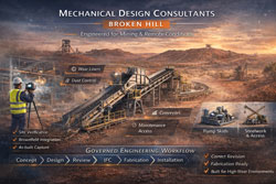
Mechanical Design Consultants Broken Hill | Mining & Industrial Engineering
Broken Hill is more than an iconic Australian mining town — it’s a living industrial environment where mechanical design means engineering solutions that withstand harsh climate, challenging site conditions and highly specialised plant requirements.
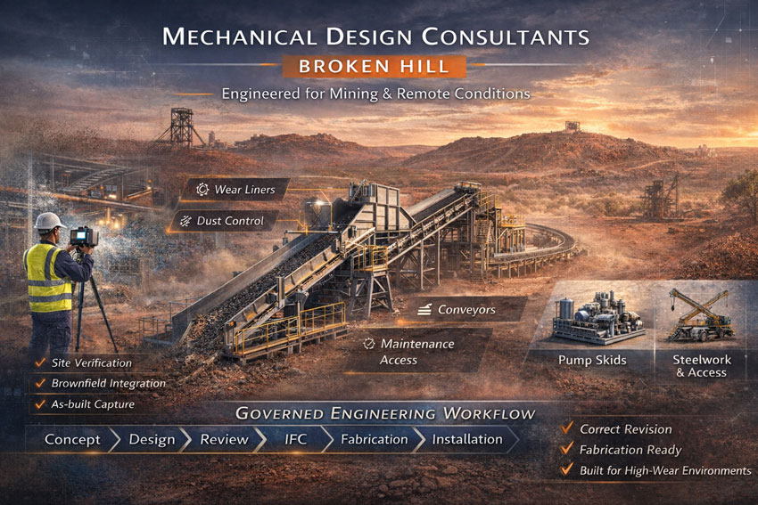
At Hamilton By Design, we provide Mechanical Design Consultants Broken Hill services that go beyond drafting. We deliver practical engineering, fabrication-ready documentation and on-site validation for projects tied to mining, materials handling, industrial process systems and structural upgrades throughout the region.
Why Mechanical Design in Broken Hill Is Unique
Broken Hill’s heritage and industrial character make it unlike typical metropolitan engineering contexts. Key factors influencing mechanical design here include:
Mining Legacy and Heavy Industry
Broken Hill’s economy is centred on mining — zinc, lead, silver and associated concentrates. Mechanical design solutions must integrate with existing plant infrastructure, high wear environments and heavy materials handling.
Harsh Climate Conditions
Extreme summer heat, dusty conditions and significant thermal expansion cycles impact equipment life and material performance. Engineering design must account for thermal stresses, corrosion resistance and maintainability over extended asset life.
Remote Logistics and Cost Sensitivity
Because Broken Hill is distant from major fabrication centres, rework and revision errors are expensive in both time and cost. Mechanical design must be right the first time with robust documentation and controlled revision systems.
Mechanical Design Services Tailored to Broken Hill Industry
Hamilton By Design provides a range of mechanical design consulting services that support Broken Hill’s key industrial and mining projects.
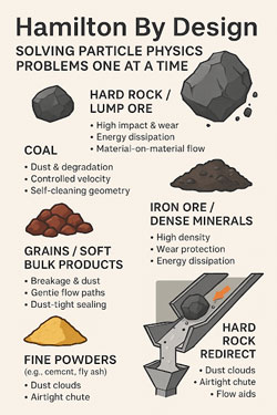
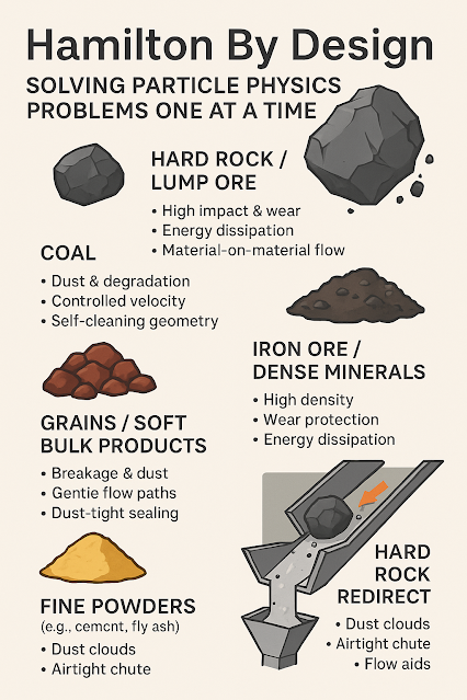
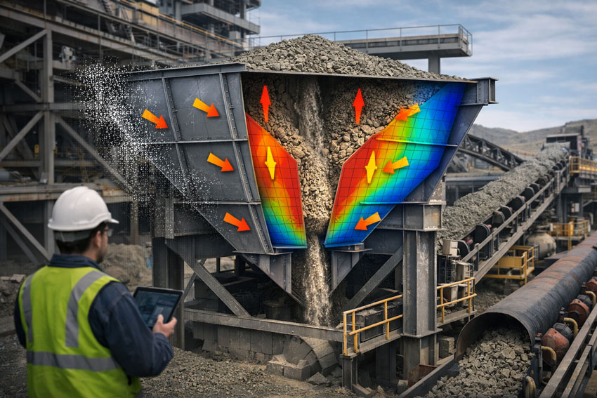
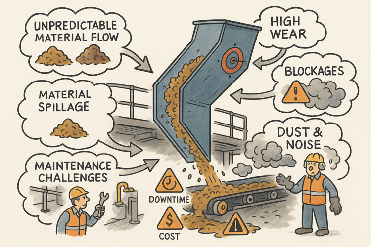
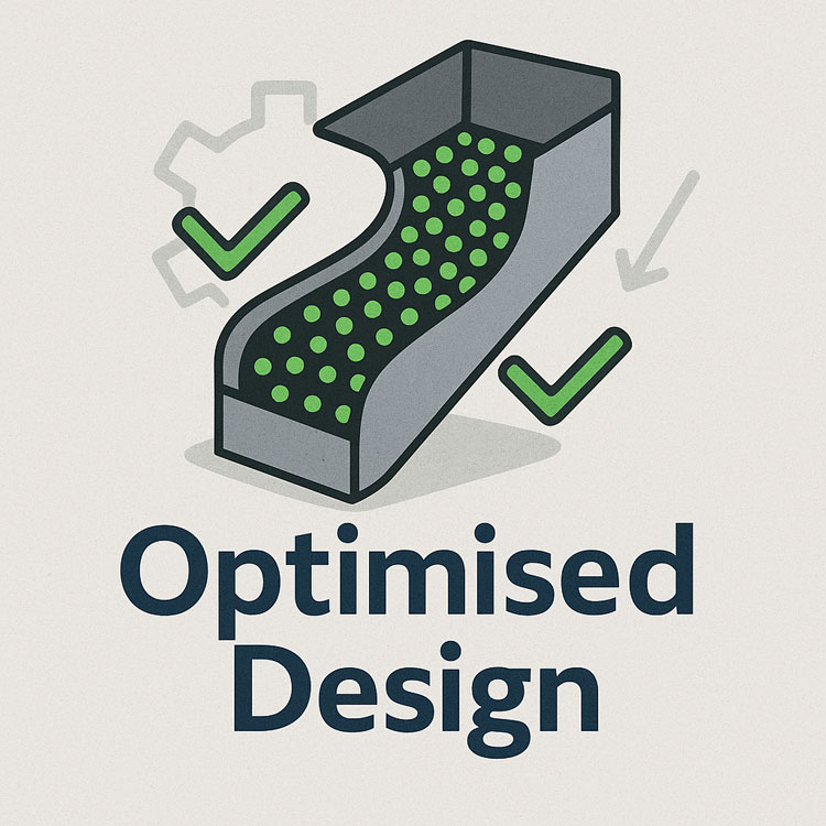
Chute Design & Transfer Systems
Material flow equipment such as chutes and transfer points are critical in mining operations. We design and optimise:
- Rock and ore chutes
- Dust-control feed transfers
- Wear-liner selection and replaceable panels
- Structural support interfaces
Our designs minimise plugging, reduce abrasion wear and improve operational reliability within dusty and high-impact environments.
Conveyor Systems
Conveyors move heavy materials across site, often over extended distances and challenging terrain. Design considerations we incorporate include:
- Conveyor frame layout and structural routing
- Loading and take-up systems
- Belt alignment and tensioning
- Access platforms and maintenance walkways
- Integration with processing plant interfaces
Our designs are 3D modelled, clash-checked and documented for first-time fabrication and installation.
Pump Skids and Process Mechanical
Hydraulic systems and processing modules require precise mechanical design, especially in mobile or modular mining applications:
- Pump skid engineering
- Piping layout and support design
- Equipment anchoring and vibration isolation
- Corrosion protection in abrasive or corrosive environments
We produce fabrication-ready documentation and coordinated layouts that fit site constraints and satisfy engineering governance.
Steelwork, Cranes and Structural Interfaces
Heavy steelwork and lifting systems are common in Broken Hill facilities. Our services include:
- Structural support and lifting frame design
- Workshop steel detailing
- Light crane and jib crane integration
- Lift points, access platforms and walkways
- Compliance with Australian steelwork and crane standards
Whether upgrading existing infrastructure or designing new installations, our mechanical design integrates structure and mechanical integrity.
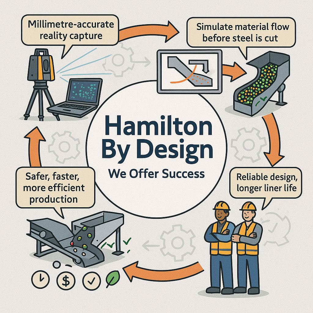
Brownfield Engineering and On-Site Validation
Many Broken Hill projects occur in live facilities with legacy equipment and tight access constraints. Hamilton By Design uses verification methods such as laser scanning and measured site capture to reduce design assumptions and ensure fit-for-site outcomes.
By combining 3D modelling with real-world site conditions, we eliminate costly guesswork and minimise installation revisions.
Governance and Documentation that Reduces Risk
High freight costs, remote fabrication and limited on-site rework options mean that mechanical design documentation must be perfectly controlled. We deliver:
- Revision-controlled issue states (Concept → Design → Review → IFC)
- Clear markups and revision histories
- Digital engineering workflows
- Maintainability-centred design
This structured approach improves contractor alignment, reduces RFIs and lowers risk across the project lifecycle.
Supporting Mining and Industrial Clients in Broken Hill
From conveyor upgrades to chute optimisation, pump skid engineering to structural crane work, Hamilton By Design applies disciplined mechanical design that solves real Broken Hill problems.
We work with:
- Mining operations and concentrator plants
- Materials handling facilities
- Industrial process upgrades
- Remote site mechanical installations
Our designs are engineered for durability, constructability and long-term performance.

Mechanical Design Consultants Broken Hill – Let’s Talk
If your project in Broken Hill or regional NSW requires experienced mechanical design consulting — whether it’s conveyors, chutes, steelwork, process modules or structural interfaces — Hamilton By Design is ready to support you with practical engineering that works on site.
Contact us today to discuss your mechanical design needs and get solutions that are precise, controlled and ready to build.