

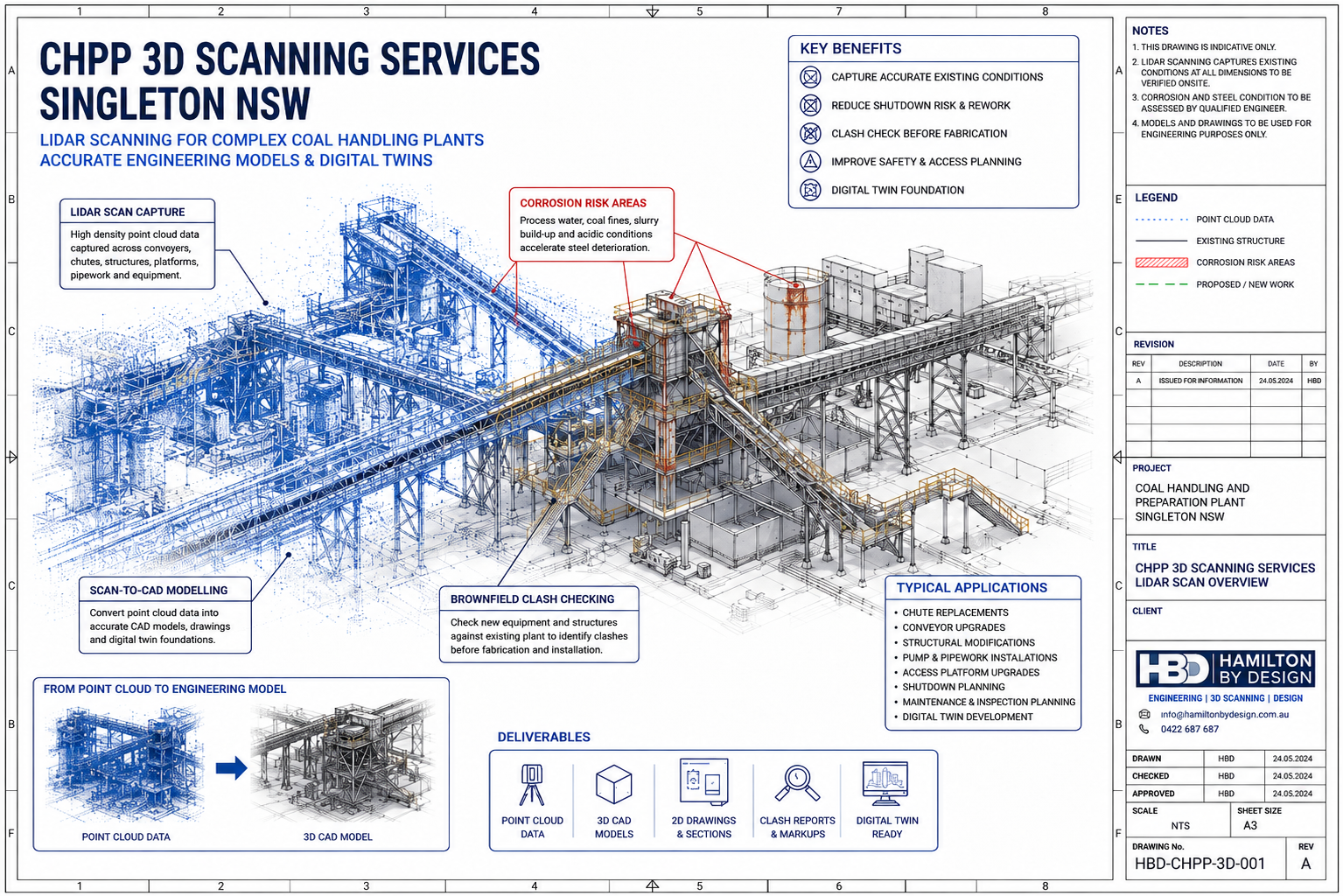
LiDAR scanning for coal handling and preparation plants creating accurate engineering models and digital twins

Coal Handling and Preparation Plants are some of the most complex, congested and maintenance-heavy assets in the Hunter Valley coal industry. Around Singleton NSW, CHPP infrastructure supports mining operations by receiving, crushing, screening, washing, separating, dewatering, storing and transferring coal through a network of conveyors, chutes, bins, tanks, pumps, screens, cyclones, pipework, gantries, access platforms and structural steel.
For engineering teams, maintenance planners and shutdown managers, the challenge is not only that the plant is complex.
The bigger challenge is that the plant is often old, modified, congested, corroded and different from the original drawings.
That is why CHPP 3D scanning services in Singleton NSW are valuable. LiDAR scanning allows coal handling and preparation plant operators to capture the real existing condition of the plant before designing upgrades, fabricating replacement parts or planning shutdown work.
A point cloud scan can help create accurate engineering models, clash checks, reverse-engineered parts, digital twin foundations, fabrication drawings and brownfield design layouts. Hamilton By Design provides engineering-grade 3D laser scanning for mining plant upgrades, helping mining operations capture accurate plant geometry before design, fabrication or shutdown work begins.
But in a CHPP, 3D scanning is not only about measuring the shape of the plant. It is also about giving engineers better visibility of risk.
The key question is not simply:
Will the new equipment fit?
The better question is:
Will the new equipment fit into an existing plant that may already be worn, corroded, modified and structurally compromised?
That is the real value of engineer-led CHPP 3D scanning.
Key Issues in CHPP Brownfield Engineering
Before rebuilding or upgrading a CHPP, the project team needs to understand the main issues that make coal preparation plants difficult to design around.
The most common problems include:
- Complex existing infrastructure
- Old or missing drawings
- OEM drawings not available
- Short shutdown windows
- Deteriorated structural steel
- Corrosion from process water and coal fines
- Hidden damage under slurry and build-up
- Difficult access for inspection and measurement
- High risk of clashes during installation
- Poor digital records of the existing plant
- Unclear load paths through old steelwork
- Multiple disciplines working in the same area
- Abrasion and wear around chutes, conveyors and slurry systems
- A need for accurate models before fabrication
- The need to turn site data into practical engineering deliverables
A CHPP is not a clean, simple industrial building. It is a working process plant where coal, water, magnetite, slurry, fines, vibration, impact, corrosion and abrasion all interact.
This makes brownfield engineering more difficult than many people expect.
Why CHPP Infrastructure Is So Complex
A coal handling and preparation plant is full of interconnected equipment. A single upgrade may involve several systems at once.
For example, replacing or modifying a transfer chute may also affect:
Conveyor belt alignment
Skirt boards
Impact beds
Head pulleys
Tail pulleys
Walkways
Access stairs
Handrails
Dust covers
Guards
Structural support frames
Lifting access
Maintenance clearances
Pipework
Cable trays
Wash-down systems
Lighting
Fire services
Drainage
Nearby platforms
This is why manual measurement is often not enough. A person with a tape measure may be able to capture a few critical dimensions, but they may not capture all the surrounding interfaces that affect the final design.
In a CHPP, the clash may not be obvious until the new item is being installed.
A handrail may be in the way.
A beam may be lower than expected.
A pipe may have been rerouted.
A chute support may have been modified.
A stair stringer may clash with a new frame.
A conveyor guard may reduce access.
A cable tray may block installation.
A worn or corroded beam may no longer be suitable for reuse.
These are the types of problems that can stop a shutdown job from going smoothly.
LiDAR scanning helps by capturing the surrounding reality of the plant, not just the one item being replaced.
The Problem with Old Drawings
Many CHPPs have been modified over decades. Drawings may exist, but they may not reflect the current site condition.
Common drawing problems include:
Original construction drawings that do not include later changes
OEM drawings that are unavailable or incomplete
PDF scans of old drawings with limited dimensional detail
2D drawings that do not show the full 3D arrangement
Hand-marked drawings that were never updated properly
Drawings that show equipment that has since been removed
Drawings that miss pipework, guards, platforms or site-run modifications
Drawings that show design intent but not as-built reality
In a brownfield CHPP project, relying only on old drawings is risky.
The drawing may show where the structure was meant to be. The plant shows where the structure actually is.
For shutdown-critical work, the real plant matters more than the old drawing.
This is one of the strongest reasons to use CHPP 3D scanning services. A LiDAR scan gives the project team a measured record of the current plant condition. That point cloud can then be used as the basis for CAD modelling, clash detection, fabrication and engineering verification.
Corrosion: The Hidden CHPP Engineering Risk
One of the biggest engineering challenges in a CHPP is the deterioration and corrosion of structural steel.
This issue deserves more attention because it changes the way brownfield design should be approached.
A CHPP is not only a congested plant. It is often a corrosive plant.
Structural steel in a coal preparation plant may be exposed to:
Process water
Recycled water
Coal fines
Slurry
Magnetite
Wash-down water
Wet coal build-up
Acidic water potential
Sulphates
Chlorides
Poor drainage
Mud and residue
Damaged coatings
Wet/dry cycling
Abrasive wear
Over time, this environment can attack beams, columns, bracing, platforms, stairways, handrails, conveyor gantries, chute supports, pipe supports, screen supports, tank supports and floor framing.
This is where the engineering problem becomes more serious.
The issue is no longer only:
Can we fit the new chute into the existing space?
The issue becomes:
Is the existing steel still suitable to carry the new chute, the new loads, the new pipework, the new platform or the modified conveyor arrangement?
That distinction matters.
LiDAR scanning can measure the geometry of the plant, but the scan needs to be reviewed with engineering judgement. A point cloud can help identify the shape, location and arrangement of steelwork. It can also help visually flag areas where further inspection may be required. But if steel section loss, corrosion, cracking or coating breakdown is suspected, the engineering team may need closer inspection, thickness checks, structural review or replacement design.
Why CHPP Steel Can Corrode Faster Than Some Hard-Rock Processing Plants
A CHPP can corrode faster than some hard-rock processing plants because of the specific combination of coal, water, fines and chemistry.
This does not mean every CHPP is worse than every iron ore or copper plant. Some copper, gold and sulphide processing plants can also be extremely corrosive, especially where acidic water, reagents or saline water are present.
However, many CHPPs have a corrosion profile that is particularly aggressive because the plant combines:
Wet processing
Fine coal
Recycled process water
Slurry deposits
Potentially acidic water
High time-of-wetness
Abrasion
Difficult cleaning access
Poor drainage pockets
Hidden build-up on structural steel
In a hard-rock crushing and screening plant, abrasion may be the dominant problem. Iron ore, for example, can be extremely abrasive. It can wear liners, chutes, screens, feeders and transfer points quickly. But parts of the plant may be relatively dry compared with a coal wash plant.
A CHPP is different because coal preparation often involves water. The plant may include dense medium circuits, sprays, wet screens, sumps, pumps, cyclones, thickeners, slurry lines, wash-down hoses and wet transfer areas.
Where water and coal fines collect on steel, corrosion risk increases.
Coal fines can hold moisture against the steel surface. If the water contains sulphates, chlorides or acidic components, the risk increases further. If the steel coating is already damaged by abrasion, impact or age, corrosion can accelerate.
This is why CHPP corrosion can be so severe around:
Wet screens
Sumps
Pump areas
Slurry pipework
Dense medium circuits
Transfer towers
Coal preparation buildings
Chute supports
Conveyor gantries
Stairways and platforms
Areas under spillage
Poorly drained steelwork
Hidden ledges and beam flanges
In many cases, the steel does not corrode evenly. The worst deterioration may be localised. A beam may look reasonable from one side but be severely corroded where coal fines have sat on the top flange. A platform may appear serviceable until the underside is inspected. A stairway may be safe in one area but weakened around the stringer base or landing connection.
This makes accurate existing-condition capture and inspection planning very important.
CHPP Corrosion Compared with Ship Loader Corrosion
It is useful to compare CHPP corrosion with a ship loader operating near salt water.
A ship loader at a coal terminal or port is exposed to a marine environment. Salt-laden air, sea spray, humidity, rain, condensation and wind-blown chlorides attack steel continuously. Marine corrosion is severe because chloride salts settle on steel surfaces, attract moisture and accelerate electrochemical corrosion.
A ship loader beside the ocean is attacked by the external environment.
A CHPP is attacked by the process environment.
The ship loader corrodes because of where it is located.
The CHPP corrodes because of what it processes.
Both are serious, but they are different.
A ship loader is often exposed to broad atmospheric corrosion across booms, gantries, rails, bogies, luffing structures, slewing structures, platforms and conveyor frames.
A CHPP may suffer from more localised and hidden corrosion where coal fines, slurry and process water sit against steel. The corrosion may be buried under build-up or hidden behind guards, pipework, chutes and access platforms.
For a ship loader, the corrosion risk is often continuous and marine-driven.
For a CHPP, the corrosion risk is often process-driven and may be worst in wet, dirty, poorly drained and hard-to-inspect areas.
This comparison strengthens the case for CHPP 3D scanning. A ship loader may need scanning for geometry, boom alignment, rail interface checks and structural access planning. A CHPP needs scanning for those reasons too, but it also needs careful attention to hidden deterioration caused by the process itself.
Why Corrosion Changes the Design Risk
When engineers design a brownfield upgrade, they often assume the existing structure can be reused. That assumption can be dangerous in a CHPP.
If a new chute, conveyor frame, pump skid, pipe rack, access platform or maintenance structure is being attached to existing steel, the condition of that steel matters.
Corrosion can reduce:
Member thickness
Bolt capacity
Weld integrity
Base plate condition
Connection strength
Load-carrying capacity
Stiffness
Fatigue resistance
Safety margin
A corroded beam may still appear to be in the correct location, but it may no longer have the same structural capacity.
This is why CHPP scanning should not be treated as a simple measurement exercise. It should be part of a broader engineering workflow.
The scan helps identify where things are.
The engineering review helps decide whether they are still suitable.
For practical project work, the design team may need to combine:
LiDAR scan data
Site photos
Visual inspection notes
Structural member identification
Thickness testing where required
Existing drawings where available
Load assessment
Fabrication constraints
Shutdown planning
Access and lifting review
Replacement steel design
This is how scanning becomes valuable engineering information rather than just a point cloud file.
How LiDAR Scanning Helps CHPP Projects
LiDAR scanning uses a laser scanner to capture millions of measured points across the plant. These points form a point cloud, which is a 3D record of the existing site.
For a CHPP, this point cloud can capture:
Conveyors
Chutes
Bins
Hoppers
Screens
Crushers
Pumps
Tanks
Pipework
Cyclones
Structural steel
Platforms
Stairs
Handrails
Guards
Cable trays
Access zones
Maintenance clearances
Surrounding obstructions
The value is that engineers can measure the plant after the scan without needing to repeatedly return to site for every missed dimension.
This is especially useful in a CHPP because access can be difficult. Some areas are at height. Some are in wet or dirty zones. Some are near process equipment. Some require permits, isolation or shutdown access.
A scan reduces the reliance on manual measurement and helps the team review the plant in 3D. For broader mining and regional support, Hamilton By Design also provides Hunter Valley mining engineering and 3D laser scanning services for mining infrastructure, CHPP facilities, structural steelwork, shutdown engineering and brownfield plant modifications.
From Point Cloud to Engineering Model
A point cloud is useful, but the real value comes when the data is turned into practical engineering deliverables.
For CHPP projects, this may include:
3D CAD models
Scan-to-CAD layouts
General arrangement drawings
Fabrication drawings
Replacement part models
Structural steel models
Access platform models
Pipework models
Chute models
Conveyor interface models
Clash checks
Sections and elevations
Shutdown planning visuals
Digital twin base models
The level of modelling should match the project need.
Not every project needs a full plant model. Sometimes the best approach is to model only the area that affects the upgrade. For example, if a chute is being replaced, the model may need the chute, conveyor belt line, surrounding steel, access platform, guards, handrails, pipework and installation envelope.
For a pump replacement, the model may need the pump base, pipe spools, valves, access space, lifting zones and nearby obstructions.
For a platform upgrade, the model may need surrounding structure, stairs, handrails, clearances, existing beams, column locations and tie-in points.
The goal is not to model everything. The goal is to model what matters.
For worn, modified or undocumented assets, Hamilton By Design can also assist with reverse engineering using 3D scanning, converting real site geometry into engineered models and drawings suitable for fabrication and installation.
Clash Detection Before Fabrication
One of the most valuable uses of CHPP 3D scanning is clash detection.
A clash can happen when the proposed design conflicts with existing plant.
Examples include:
A new chute clashes with existing steel.
A pipe spool clashes with a handrail.
A platform clashes with a conveyor guard.
A stairway clashes with a cable tray.
A pump skid clashes with existing pipework.
A replacement frame clashes with a beam.
A crane lift path clashes with structure.
A maintenance access route is blocked.
A fabricated component cannot be installed because there is no clearance.
These problems are expensive when they are discovered during shutdown.
By placing the new design into the scanned plant model before fabrication, the project team can detect many of these problems earlier.
This helps reduce:
Site rework
Hot work during shutdown
Fabrication errors
Delayed installation
Lost production
Emergency redesign
Unplanned labour
Safety exposure
Disputes between designer, fabricator and installer
For CHPPs around Singleton and the Hunter Valley, this is one of the strongest reasons to invest in scanning before design is finalised.
CHPP 3D Scanning for Digital Twins
A digital twin begins with reliable existing-condition data.
In a CHPP, that data is often missing, outdated or scattered across drawings, site knowledge, OEM manuals, markups, inspection reports and maintenance records.
LiDAR scanning can create the spatial foundation for a CHPP digital twin. The point cloud or scan-derived CAD model can show where assets are located, how they relate to each other and what the plant looked like at a point in time.
Over time, this model can be developed further with:
Asset numbers
Equipment information
Maintenance data
Inspection notes
Structural condition records
Corrosion zones
Shutdown history
Upgrade history
Replacement part models
Pipework information
Access and safety information
This does not need to happen all at once. A practical digital twin can start with a targeted scan of a problem area and grow over time.
For CHPP operators, the digital twin concept is useful because the plant constantly changes. Every shutdown, repair and modification can make the old drawing set less reliable. A scan-based model gives the site a better foundation for future engineering work.
Hamilton By Design has also written about how LiDAR scanning is transforming mining process plants, including how scan data can support accurate plant records, digital engineering workflows and digital twin development.
Tools That Assist CHPP 3D Scanning and Engineering
A strong CHPP scanning and design workflow may use several tools together.
FARO laser scanning can capture detailed plant geometry quickly and accurately.
FARO SCENE can be used to register scan data and manage point clouds.
Autodesk ReCap can prepare point cloud files for use in CAD and coordination workflows.
SolidWorks can be used for mechanical design, reverse engineering, chute modelling, guarding, platforms, replacement parts and fabrication drawings.
AutoCAD can be used for 2D drawings, markups, layouts, sections and elevations.
Autodesk Inventor can support mechanical plant modelling and brownfield design workflows.
Navisworks can be used for clash detection and model coordination.
Rocky DEM can assist where coal flow, chute performance, wear zones, blockage risk or transfer performance needs to be reviewed.
3DEXPERIENCE / ENOVIA can support CAD data management, revision control and engineering collaboration.
The important point is that the scanner is only one part of the solution. The real value comes from combining scan data with mechanical design, drafting, engineering review and practical shutdown knowledge.
CHPP Areas That Benefit from 3D Scanning
CHPP 3D scanning can be applied to many plant areas, including:
Raw coal handling systems
Product coal conveyors
Rejects conveyors
Transfer towers
Preparation buildings
Screen houses
Crusher areas
Dense medium circuits
Cyclone areas
Magnetite systems
Pump areas
Thickeners
Slurry pipework
Chute replacements
Bin and hopper areas
Conveyor gantries
Access platforms
Stairways and walkways
Structural steel tie-in points
Maintenance access zones
Shutdown work fronts
The best projects for scanning are usually the ones where the cost of getting it wrong is high.
If a fabricated item must fit first time, scanning is valuable.
If the drawings are unreliable, scanning is valuable.
If the plant is congested, scanning is valuable.
If the existing steel may be corroded or modified, scanning is valuable.
If the shutdown window is tight, scanning is valuable.
Why Singleton CHPP Operators Need Accurate Site Data
Singleton and the broader Hunter Valley have long-established coal mining and processing infrastructure. Many plants have been operating, modified, maintained and upgraded over many years.
That history creates a brownfield engineering challenge.
The plant may have started with good drawings. But after years of repairs, replacement parts, site-run changes and shutdown modifications, the real site condition may be different.
For operators, this creates uncertainty.
The uncertainty affects:
Design
Procurement
Fabrication
Installation
Shutdown planning
Structural review
Maintenance access
Safety planning
Cost control
Project schedule
LiDAR scanning reduces that uncertainty by capturing the existing plant before decisions are locked in.
Why Use Hamilton By Design for CHPP 3D Scanning?
Hamilton By Design provides engineer-led 3D scanning, CAD modelling, reverse engineering and mechanical design support for industrial and mining clients.
For CHPP work, the key advantage is that the scan is captured with the engineering outcome in mind.
The objective is not simply to provide a point cloud. The objective is to support better engineering decisions.
Hamilton By Design can assist with:
CHPP LiDAR scanning
Point cloud registration
Scan-to-CAD modelling
SolidWorks modelling
AutoCAD drafting
Mechanical design
Reverse engineering
Chute and conveyor interface modelling
Access platform design support
Structural drafting support
Fabrication drawings
Brownfield clash checking
Digital twin base models
Shutdown planning support
For coal handling and preparation plants, this is important because the person scanning the plant needs to understand what the engineering team will need later.
A poor scan may miss the tie-in points.
A poor scan may miss the surrounding clash risks.
A poor scan may not capture access clearances.
A poor scan may not record enough of the corroded or modified structure.
A poor scan may create a point cloud that is difficult to use for design.
Engineer-led scanning improves the chance that the right areas are captured the first time.
Practical CHPP 3D Scanning Workflow
A typical CHPP scanning workflow may include the following steps.
1. Define the engineering problem
The first step is to identify what the scan needs to support. Is the job a chute replacement, conveyor upgrade, pipework modification, pump replacement, access platform, structural review, digital twin or shutdown package?
2. Review available drawings
Existing drawings are useful, even if they are outdated. They help identify equipment names, gridlines, levels, drawing history and likely tie-in points.
3. Plan the scan
Scan positions are selected to capture the target area and surrounding interfaces. In a CHPP, multiple scan positions are usually required because of obstructions.
4. Capture the site
The scanner captures the plant geometry from multiple locations. Photos and site notes may also be collected to support later modelling and review.
5. Register the point cloud
The scans are aligned into a single coordinate system and checked for accuracy.
6. Review the scan
The engineering team reviews the point cloud to identify relevant geometry, clashes, access issues and areas requiring further inspection.
7. Build the CAD model
Selected plant items are modelled from the point cloud. The level of detail depends on the project.
8. Insert the new design
The proposed chute, conveyor, platform, pipework, pump skid or replacement part is placed into the existing-condition model.
9. Check clashes and access
The team checks for physical clashes, installation clearance, maintenance access and possible structural issues.
10. Produce deliverables
Deliverables may include point clouds, 3D models, drawings, clash reports, fabrication drawings, sections, elevations and digital twin base models.
The Strongest Message for CHPP Operators
For CHPP operators, the strongest message is this:
Do not design from old drawings alone. Scan the plant, model the real conditions and review the existing steel before fabrication begins.
Coal handling and preparation plants are complex enough when everything is in good condition. They become much more difficult when the existing structure is corroded, worn, modified or hidden under coal build-up.
LiDAR scanning helps reduce risk by giving engineers accurate site data. But the best results come when scanning is combined with mechanical design, drafting, structural awareness and practical brownfield engineering experience.

Conclusion
CHPP 3D scanning services in Singleton NSW provide an important engineering tool for coal handling and preparation plant operators.
The value is not only in creating a point cloud. The value is in capturing the real plant condition before design, fabrication and shutdown work begins.
In a CHPP, the biggest risks often come from the existing plant itself. The infrastructure is congested. The drawings may be unreliable. OEM information may not be available. Shutdown windows are short. Access is difficult. Steelwork may be corroded from process water, coal fines, slurry and acidic conditions. Wear and corrosion may be hidden under build-up.
That means the engineering team needs accurate site data before making design decisions.
LiDAR scanning supports:
Accurate existing-condition capture
Brownfield design confidence
Clash detection
Reverse engineering
Fabrication accuracy
Shutdown planning
Digital twin development
Structural review planning
Reduced reliance on old drawings
Better communication between engineers, fabricators and site teams
For Singleton CHPPs and Hunter Valley coal operations, this can reduce project risk, improve installation planning and help create a more reliable engineering record of the plant.
The final message is simple:
A CHPP is not just complex. It is complex, wet, abrasive, corrosive and constantly changing. 3D scanning helps capture the truth of the plant before the next engineering decision is made.
Talk to Us – Contact Us
Our clients:


