Material Handling: Bucket Elevator Scan, Design, Build and Install

3D LiDAR scanning to CAD modelling workflow for a bucket elevator system in an industrial material handling plant

An Engineering-Led Approach for Brownfield Industrial Environments

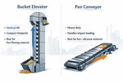
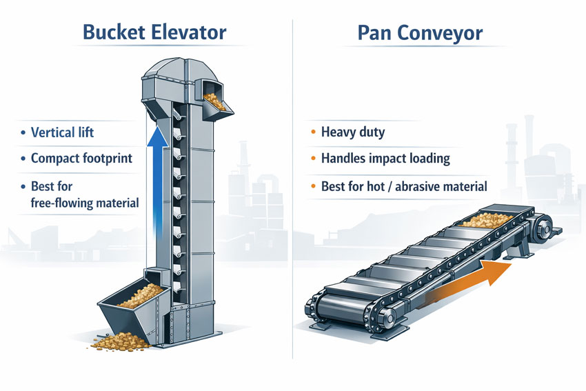
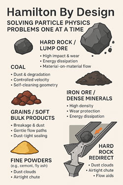
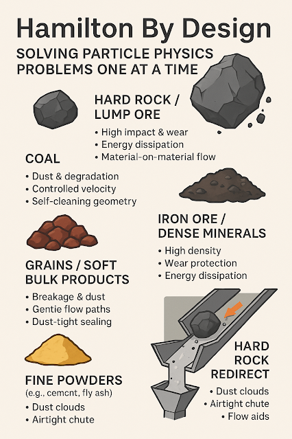
Bucket elevators are a fundamental component of bulk material handling systems, providing an efficient and reliable method for the vertical transport of materials such as ores, grains, cement, and industrial powders. Despite their apparent simplicity, the successful design and installation of bucket elevators within existing (brownfield) facilities presents significant engineering challenges. These challenges typically arise from undocumented modifications, limited access, and the inherent complexity of integrating new infrastructure into legacy plant environments.

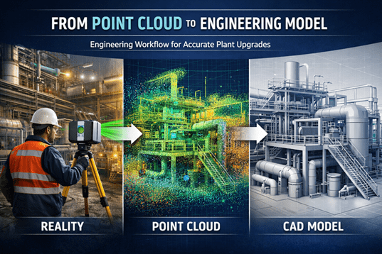
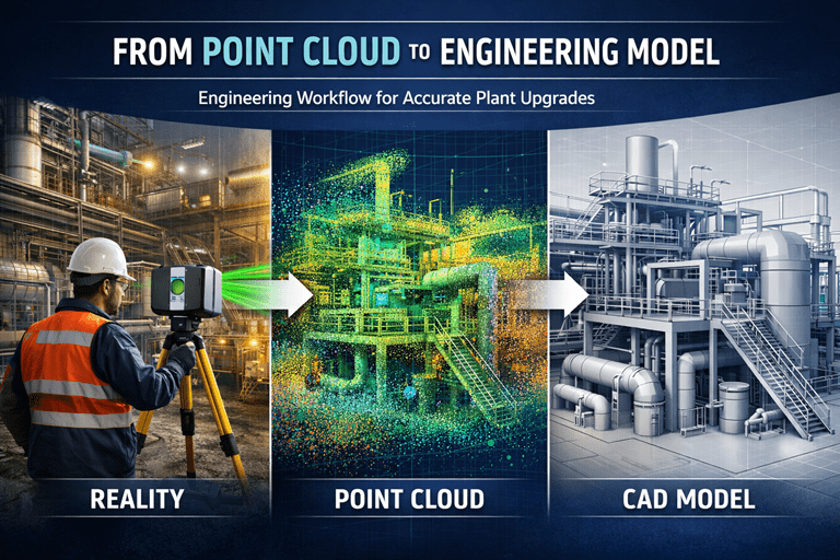
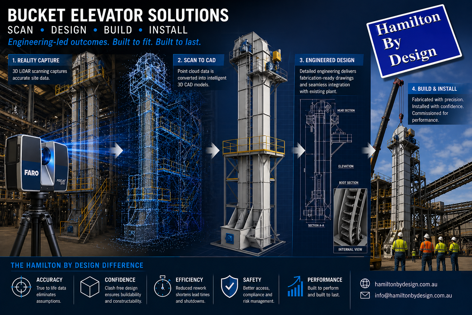
This paper outlines an engineering-led methodology adopted by Hamilton By Design, incorporating 3D LiDAR scanning, scan-to-CAD modelling, and fabrication-ready design to deliver a complete scan, design, build, and install solution for bucket elevator systems.


3D CAD Modelling Australia service banner for Hamilton By Design

Limitations of Traditional Design Methodologies

Conventional approaches to bucket elevator design often rely on outdated drawings, manual site measurements, and engineering assumptions regarding existing plant conditions. While these methods may be adequate for greenfield developments, they are frequently inadequate in brownfield environments.

Common issues associated with traditional methodologies include:

  • Dimensional inaccuracies leading to misalignment during installation
  • Increased fabrication rework due to unforeseen clashes
  • Extended shutdown durations and associated production losses
  • Elevated safety risks resulting from poor integration with existing infrastructure

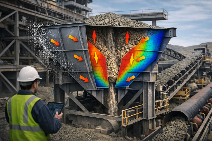
In material handling systems, particularly those involving rotating equipment and vertical conveyance, dimensional accuracy is critical. Minor deviations can result in significant operational inefficiencies, including premature wear, belt tracking issues, and mechanical failure.


Engineering-Grade 3D LiDAR Scanning

To address these challenges, an engineering-grade 3D LiDAR scanning process is employed to capture a high-resolution, spatially accurate representation of the existing plant environment. This process generates a point cloud dataset that reflects the true geometry of all visible structures, equipment, and interfaces.

The application of LiDAR scanning provides the following advantages:

  • Accurate capture of structural steelwork, platforms, and existing material handling systems
  • Identification of spatial constraints and potential clashes prior to design development
  • Reliable definition of tie-in points for new equipment
  • Reduction in reliance on assumptions and manual measurement

Importantly, the point cloud dataset is treated as an engineering input, rather than a visual reference. This distinction ensures that all subsequent design activities are grounded in verified, real-world data.


Scan-to-CAD Modelling and Engineering Design

Following data acquisition, the point cloud is processed and converted into a structured, parametric CAD model. This scan-to-CAD workflow enables the development of detailed engineering designs that accurately reflect existing site conditions.

Typical deliverables include:

  • Three-dimensional parametric models suitable for engineering analysis and coordination
  • General Arrangement (GA) drawings illustrating system layout and interfaces
  • Detailed sections and elevations through critical components
  • Interface definitions with existing conveyors, chutes, and structural systems

This approach facilitates seamless integration of the bucket elevator with existing plant infrastructure. Furthermore, it enables multidisciplinary coordination, ensuring alignment between mechanical, structural, and operational requirements.

A key differentiator of this methodology is the focus on producing fabrication-ready outputs, rather than conceptual or visual models. This ensures that the design intent can be directly translated into manufacturable components.


Engineering Considerations in Bucket Elevator Design

The design of a bucket elevator system must address a range of mechanical, structural, and operational factors.

Mechanical Design Parameters

  • Selection of belt or chain systems based on material characteristics and throughput requirements
  • Determination of bucket spacing, capacity, and configuration
  • Design of head pulley assemblies and drive systems
  • Specification of boot sections, including tensioning and clean-out provisions

Structural Integration

  • Design of support frames and load transfer mechanisms
  • Assessment of existing structural capacity and required reinforcements
  • Compliance with relevant standards, including AS 1657 for access and maintenance systems

Operational and Maintenance Considerations

  • Material flow behaviour and potential for blockages
  • Dust containment and environmental controls
  • Provision of safe access for inspection, maintenance, and replacement activities

By integrating scan data with engineering analysis, the resulting design is optimised for both performance and constructability within the constraints of the existing facility.


Fabrication and Quality Assurance

The transition from design to fabrication is significantly enhanced by the availability of accurate, detailed engineering documentation. Fabrication drawings derived from scan-based models provide a high degree of confidence in component fitment and assembly.

Key benefits include:

  • Reduction in fabrication errors and rework
  • Improved efficiency in workshop processes
  • Accurate material take-offs and procurement planning
  • Enhanced quality assurance through alignment with verified design data

Engineering oversight during fabrication ensures that all components meet specified tolerances and performance requirements.


Installation and Commissioning

Installation of bucket elevator systems within operational facilities is typically constrained by limited shutdown windows and restricted access. As such, careful planning and coordination are essential.

An engineering-led installation approach includes:

  • Development of detailed installation methodologies and sequencing
  • Planning of lifting operations and access requirements
  • Verification of alignment and fitment using scan data
  • Provision of on-site engineering support during critical installation phases

The use of pre-validated design data significantly reduces installation risk, minimises delays, and ensures a more efficient commissioning process.


Benefits of an Integrated Scan, Design, Build and Install Approach

The integration of LiDAR scanning, engineering design, and fabrication support provides a number of measurable benefits:

  • Reduced project risk through improved dimensional accuracy
  • Enhanced constructability and reduced fabrication rework
  • Shorter installation durations and reduced plant downtime
  • Improved coordination between engineering, fabrication, and site teams

For project stakeholders, this approach delivers greater certainty in both project outcomes and timelines.


Applications in Industry

This methodology is applicable across a range of industries where bulk material handling systems are utilised, including:

  • Mining and mineral processing operations
  • Agricultural and grain handling facilities
  • Cement and bulk powder processing plants
  • Recycling and industrial manufacturing environments

It is particularly valuable in brownfield projects involving upgrades, retrofits, or replacement of existing bucket elevator systems.


Conclusion

The successful implementation of bucket elevator systems in brownfield environments requires a departure from traditional design methodologies. By adopting an engineering-led approach grounded in accurate spatial data, it is possible to significantly reduce project risk and improve overall outcomes.

Hamilton By Design provides a comprehensive solution that integrates 3D LiDAR scanning, scan-to-CAD modelling, and fabrication-ready design. This approach ensures that bucket elevator systems are not only theoretically sound but also practically deliverable within the constraints of real-world industrial environments.

3D LiDAR scanning and 3D modelling service button โ€” laser scanner capturing a point cloud for engineering and CAD modelling
Mechanical engineering services

Contact Us – Talk to Us


Hamilton By Design logo displayed on a blue tilted rectangle with a grey gradient background

E-Mail: info@hamiltonbydesign.com.au

Mining Infrastructure Design Discussions โ€“ SolidWorks and Industrial Engineering

Engineering workflow showing industrial laser scanning, point cloud data, and a CAD model used for plant upgrade design.

Modern mining and industrial infrastructure projects increasingly rely on advanced digital engineering tools to support plant design, equipment upgrades, and infrastructure development. Engineers working in mining environments must often design and model complex systems including materials handling equipment, processing plant infrastructure, and structural steel frameworks.

Engineer using a laser scanner capturing an industrial facility, converting scan data into a point cloud and engineering CAD model.

One of the most commonly used design platforms for mechanical engineering and plant infrastructure modelling is SolidWorks, which allows engineers to develop detailed 3D assemblies and fabrication-ready engineering drawings.

At Hamilton By Design, many projects involve the integration of modern digital engineering workflows with practical industry experience. These workflows often include:

  • Mechanical design for mining infrastructure
  • Bulk materials handling system design
  • Industrial plant layout modelling
  • Point cloud modelling from laser scanning
  • Engineering design for plant upgrades and shutdown projects

Engineering Design in Mining Infrastructure

Mining infrastructure often includes complex systems such as conveyors, transfer stations, processing equipment, and plant structures. Designing or upgrading these systems requires accurate modelling of both existing infrastructure and proposed modifications.

Modern engineering teams frequently combine several technologies during the design process, including:

  • 3D laser scanning to capture existing plant conditions
  • Point cloud modelling to represent real-world infrastructure
  • CAD modelling using platforms such as SolidWorks
  • Engineering drawings and documentation for fabrication and construction

These tools allow engineers to develop more accurate designs and reduce risks when implementing plant modifications or shutdown upgrades.


Engineering Discussions and SolidWorks Design Examples

Engineering professionals often share practical insights, modelling approaches, and design workflows through technical blogs and engineering discussion platforms.

For those interested in SolidWorks modelling techniques, mining infrastructure design concepts, and materials handling engineering, additional discussions can be found on the following engineering blog:

Mining Infrastructure โ€“ SolidWorks Design
https://mininginfrastructuresolidworksdesign.blogspot.com/

The blog explores various topics including mechanical design workflows, industrial equipment modelling, and practical engineering approaches used when designing plant infrastructure.


Supporting Mining Engineering Projects

Hamilton By Design supports mining and industrial operators with engineering services that include mechanical design, infrastructure modelling, and reality capture technologies such as laser scanning.

Learn more about our engineering-grade scanning and modelling services:

Engineering-Grade 3D Laser Scanning for Mining and Industrial Projects
https://www.hamiltonbydesign.com.au/home/engineering-grade-3d-laser-scanning-mining-industrial/

3D Laser Scanning Across Australia
https://www.hamiltonbydesign.com.au/home/engineering-services/3d-laser-scanning/3d-laser-scanning-across-australia/

Capturing Existing Conditions Before Plant Upgrades
https://www.hamiltonbydesign.com.au/capture-existing-conditions-before-plant-upgrades/


3D LiDAR scanning and 3D modelling service button โ€” laser scanner capturing a point cloud for engineering and CAD modelling
Mechanical engineering services

Engineering Knowledge Sharing

Engineering blogs and technical discussion platforms provide an opportunity for engineers, designers, and industry professionals to share knowledge about real-world engineering challenges.

By combining practical industry experience with modern digital engineering tools, the mining and industrial sectors continue to improve the way infrastructure is designed, documented, and upgraded.

For more engineering discussions on SolidWorks design and mining infrastructure modelling, visit:

https://mininginfrastructuresolidworksdesign.blogspot.com

3D CAD Modelling Australia service banner for Hamilton By Design

Designing Bucket Elevators vs Pan Conveyors in Industrial Material Handling

Engineering comparison diagram showing a bucket elevator lifting bulk material vertically and a pan conveyor transporting material horizontally.

Bucket Elevator vs Pan Conveyor Design | Industrial Material Handling Engineering

In bulk material handling industries such as mining, cement production, grain processing, and industrial manufacturing, selecting the right conveying system is critical to reliability, maintenance efficiency, and operating cost. Two commonly used systems are bucket elevators and pan conveyors. While both systems move bulk material efficiently, they are designed for very different operating conditions and material characteristics.

Understanding the difference between the two systems helps engineers select the correct solution for the application.


Bucket elevator vs pan conveyor industrial material handling comparison infographic.

What is a Bucket Elevator?

A bucket elevator is a vertical conveying system designed to lift bulk materials using a series of buckets attached to either a belt or chain. The buckets scoop material from the boot section and carry it upward to the discharge point.

Bucket elevators are widely used where material must be lifted vertically in a compact footprint.

Key Components

Buckets (steel, nylon, or HDPE)
Belt or chain drive
Boot section (material inlet)
Head section with drive and discharge
Casing or elevator trunking

Typical Applications

Grain handling
Fertiliser plants
Cement and lime processing
Mining concentrate handling
Sand, ash, or powder transport

Advantages

Efficient vertical lifting
Small plant footprint
High throughput capacity
Energy efficient for vertical transport

Limitations

Not ideal for very abrasive or large lump materials
Sensitive to overloading and blockages
Requires careful alignment and maintenance


What is a Pan Conveyor?

A pan conveyor, often called an apron conveyor, transports material horizontally or on shallow inclines using overlapping steel pans attached to heavy-duty chains.

The pans form a continuous moving surface that carries material along the conveyor frame.

Pan conveyors are commonly used in harsh industrial environments where materials are heavy, hot, or abrasive.

Key Components

Steel pans or plates
Heavy-duty conveyor chains
Sprockets and drive system
Conveyor frame
Impact loading zone

Typical Applications

Clinker transport in cement plants
Mining ore handling
Hot ash handling
Crusher discharge conveyors
Furnace feed systems

Advantages

Handles very heavy and abrasive materials
Suitable for impact loading
Reliable in harsh environments
Can operate at slow controlled speeds

Limitations

Larger footprint
Higher capital cost
More power consumption than bucket elevators


Key Differences Between Bucket Elevators and Pan Conveyors

Bucket Elevator
Vertical conveying system
Best for fine to medium bulk materials
Compact footprint
High energy efficiency for vertical transport
Requires controlled loading

Pan Conveyor
Horizontal or inclined conveying system
Handles heavy, abrasive or hot materials
Larger footprint
More robust construction
Handles high impact loading


When to Choose a Bucket Elevator

A bucket elevator is typically the preferred solution when:

Material must be lifted vertically
Plant space is limited
The material is free-flowing
Throughput is high but impact loading is low

Examples include grain silos, cement plants, fertiliser plants, and powder handling systems.

In these situations, bucket elevators provide a compact and energy-efficient solution.


When to Choose a Pan Conveyor

A pan conveyor is the better choice when:

Material is coarse, hot, or abrasive
There is high impact loading
The conveyor must operate continuously in harsh conditions
Reliability is more important than plant footprint

Examples include crusher discharge conveyors, furnace feed systems, clinker transport, and mining ore handling.

Pan conveyors are designed to survive the harshest bulk material handling environments.


Engineering Design Considerations

When designing either system, engineers must consider the following:

Bulk material characteristics
Lump size distribution
Abrasiveness
Moisture content
Throughput requirements
Loading conditions
Maintenance access
Structural support

Modern projects often integrate 3D laser scanning and point cloud modelling to ensure conveyors fit within existing plants and connect correctly to existing infrastructure. This approach reduces installation risk and helps engineers verify clearances, structural loads, and maintenance access before fabrication.

3D LiDAR scanning and 3D modelling service button โ€” laser scanner capturing a point cloud for engineering and CAD modelling
Mechanical engineering services

Hamilton By Design logo displayed on a blue tilted rectangle with a grey gradient background

Engineering Support for Conveyor Design

Hamilton By Design supports industrial projects with:

Mechanical conveyor design
3D laser scanning of existing plants
Conveyor chute and transfer design
Structural steel and support frames
Inspection and maintenance optimisation

Whether designing a bucket elevator for vertical material handling or a heavy-duty pan conveyor for mining operations, selecting the correct system is critical to long-term reliability and operational efficiency.


Name
Would you like us to arrange a phone consultation for you?
Address
3D CAD Modelling Australia service banner for Hamilton By Design

Designing Chutes for Easy Maintenance: The Hamilton by Design Approach

Engineering infographic explaining chute design challenges for coal, iron ore, hard rock, grains, and powders.

In high-wear environments such as mining, minerals processing and bulk material handling, chutes are constantly subject to abrasion, material impact and scraper wear. But too often, chute design prioritises material flow while overlooking how maintenance crews will access, replace, or adjust wear components and scrapers safely and efficiently.

At Hamilton by Design Co., we engineer chutes not only for performanceโ€”but for maintainability. Because downtime, difficult access and costly labour arenโ€™t just inconvenientโ€”they cut straight into your production goals.


Why Maintenance-Friendly Chute Design Matters

Traditional chutes often have one thing in common: theyโ€™re hard to service. Common pain points include:

  • Poor access to internal wear liners
  • Limited clearance for scraper removal/replacement
  • Unsafe confined spaces for maintenance crews
  • Complex disassembly for simple tasks

When maintenance teams struggle to reach components, the outcome is predictable: reduced uptime, increased safety risk and higher long-term operating costs.

A better design not only minimises wearโ€”it facilitates wear replacement.


Infographic titled โ€œHamilton By Design โ€“ Solving Particle Physics Problems One at a Timeโ€ showing material types like coal, hard rock, iron ore, grains, and fine powders with chute design considerations.

Key Principles in Maintainable Chute Design

1. Access Firstโ€”Flow Second

At Hamilton by Design we always ask:
Can a technician reach the wear components safely and efficiently?

Practical solutions we use include:

  • Strategic access doors positioned adjacent to high-wear zones
  • Removable panels with quick-release fasteners
  • Tool-less entry where safe to do so

Simple changes like these reduce maintenance time dramatically.


2. Clearance and Space for Wear Component Removal

Every chute design should consider how a liner panel, scraper blade or skirting board will be removed and replaced. That means:

  • Adequate clearance for lifting gear
  • Doors that open wide enough for component extraction
  • Recessed bolt access to avoid removal obstacles

This forward planning translates directly to lower labor hours and fewer workarounds.


3. Modular Wear Components

Instead of large, welded-in liners that require cut-out replacement, we prefer:

  • Modular liner segments
  • Bolted scraper shoes
  • Replaceable wear strips

Modularity means teams can replace only whatโ€™s wornโ€”without disassembling the whole chute.


4. Scrapers Designed for Easy Swap-Out

Scraper blades are one of the most frequently replaced items in feed and transfer chutes. Good design ensures:

โœ” blades are accessible
โœ” blades can be removed with minimal tools
โœ” adjustment points are visible and reachable

Hamilton by Design uses engineered scraper blocks and mounting systems that:

  • protect the blade from downstream impacts
  • allow quick blade indexing or change-out
  • can be serviced from outside the chute where possible

5. Safety and Compliance Built In

Maintenance isnโ€™t just easierโ€”it must also be safer. Thatโ€™s why our designs include:

๐Ÿ”น lockable access panels
๐Ÿ”น clear entry/egress paths
๐Ÿ”น adequate lighting and fall protection points
๐Ÿ”น confined-space considerations where relevant

Taking safety off the critical path keeps your team productive and compliant.


Mining hopper in a transfer station shown in cutaway, illustrating steady-state material flow, structural load distribution, and engineered hopper design.

Putting It All Together: Benefits You Can Measure

When chute design accommodates maintenance needs, the benefits are real:

OutcomeBenefit
Shorter maintenance windowsMore uptime
Easier scraper changesLower labour cost
Modular wear partsReduced inventory waste
Lower safety riskFewer incidents and stoppages
Better flow + maintainabilityHigher throughput

Hamilton by Design: Chutes Built for the People Who Maintain Them

At Hamilton by Design Co., we recognise that chutes donโ€™t just sit thereโ€”they work hard, and your team works hard to keep them running.

Thatโ€™s why our engineers consider:

โœ… material properties
โœ… wear patterns
โœ… maintenance access
โœ… scraper replacement
โœ… safety & ergonomics

all from the earliest design stage.

If your operation is battling hard-to-maintain chutes, or you want chutes that perform and serve your maintenance crews well, weโ€™d love to help.

Contact Hamilton by Design today for a design review or quote.


3D LiDAR scanning and 3D modelling service button โ€” laser scanner capturing a point cloud for engineering and CAD modelling
Mechanical engineering services
Name
Would you like us to arrange a phone consultation for you?
Address


3D LiDAR scanning and 3D modelling service button โ€” laser scanner capturing a point cloud for engineering and CAD modelling
Mechanical engineering services
Finite Element Analysis (FEA) engineering simulation button
Mechanical engineering services
3D LiDAR scanning and 3D modelling service button โ€” laser scanner capturing a point cloud for engineering and CAD modelling
Mechanical engineering services
Finite Element Analysis (FEA) engineering simulation button
Mechanical engineering services

Industrial Machinery & Plant Systems Design

Industrial Machinery & Plant Systems Design

Consulting-led mechanical engineering for mining, processing and manufacturing operations


Practical, engineered solutions for brownfield and greenfield industrial facilities

Hamilton By Design provides consulting-led mechanical engineering for complex industrial systems across mining, mineral processing, manufacturing and heavy industry.

We specialise in designing, upgrading and optimising machinery and plant systems that must perform reliably under real operating conditions โ€” high loads, abrasive materials, continuous duty cycles, demanding shutdown windows and strict compliance requirements.

Whether you’re introducing new equipment, modifying existing systems or expanding production capacity, we help you move from concept to construction with clarity, accuracy and confidence.


How We Support Your Plant & Machinery Projects

Our consulting team works from the problem outward โ€” understanding your operational objectives, constraints and shutdown timelines before we begin design.

We help clients:

  • Upgrade brownfield equipment while minimising downtime and rework
  • Design new machinery and plant systems aligned to production targets
  • Resolve recurring performance, wear, or reliability issues through redesign
  • Integrate OEM equipment into complex existing facilities
  • Coordinate mechanical, structural and access requirements in one model
  • Prepare fabrication-ready documentation that installers and workshops can rely on

Our engineering process combines real site experience, 3D CAD modelling, FEA where needed, and โ€” for brownfield work โ€” engineer-led 3D LiDAR scanning to ensure accuracy.


What We Design

Hamilton By Design delivers mechanical systems and plant layouts across a wide range of industrial applications:

Bulk Materials Handling Systems

  • Conveyors (fixed, shiftable, overland, tripper gantries)
  • Transfer towers and conveyor galleries
  • Chutes, hoppers, bins and wear lining systems
  • Feeders, vibratory equipment and discharge systems

Processing & Production Equipment

  • Screens, crushers, mills and separation equipment interfaces
  • Pumping systems, pipework, manifolds and slurry line transitions
  • Tanks, vessels, agitators and mechanical supports
  • Mechanical upgrades to maximise throughput or reliability

Plant Layouts & System Integration

  • Space-constrained brownfield layouts
  • New plant expansions and tie-ins
  • Mechanicalโ€“structural interface design
  • Access, maintenance and safety systems

Support Systems & Ancillary Equipment

  • Platforms, walkways, stairs and guarding
  • Maintenance stands, frames, skids and lifting/handling devices
  • Mobile and fixed equipment support structures

If it moves material, processes ore, mounts equipment or supports production, we can help design it.


Our Design Approach

Industrial plant design is never one-size-fits-all. Every project has operational realities, shutdown limits and site constraints. Our approach reflects that:

1. Understand the Operating Environment

We begin by understanding:

  • Production goals
  • Wear mechanisms
  • Availability targets
  • Maintenance constraints
  • Compliance and site standards

This ensures the design is grounded in how the plant is actually used โ€” not how it looks on paper.

2. Capture Accurate Existing Conditions

For brownfield sites, we integrate 3D LiDAR scanning to ensure all tie-ins, clearances and interfaces match reality.
This significantly reduces rework, clashes and on-site modification.

3. Develop Practical Mechanical Concepts

We generate design options that consider:

  • Material flow
  • Access and maintenance
  • Installation sequence
  • Transport and modularisation
  • Cost, complexity and risk

Options are presented with pros and cons so you can decide the best path forward.

4. Engineer the Details

Using SolidWorks and analysis tools, we refine:

  • Load paths and structural capacity
  • Wear management and replaceability
  • Supports, fixings and serviceability
  • Safety, guarding, access and compliance
  • Liner systems and flow optimisation

5. Verify Performance & Reliability

Where appropriate, we perform:

  • FEA for stress, fatigue and buckling
  • Check calculations for structural and mechanical compliance
  • Flow and material behaviour assessments
  • Vibration or modal checks for dynamic equipment

6. Produce Fabrication & Installation Documentation

We deliver:

  • 3D models
  • GA drawings
  • Fabrication details
  • BOMs and cutting lists
  • Installation notes
  • Tie-in and interface details

All documentation is prepared with fabricators, installers and shutdown teams in mind.


Where This Service Adds the Most Value

Hamilton By Designโ€™s industrial machinery and plant system design services are ideal for:

  • Shutdown-driven upgrades where every hour matters
  • Debottlenecking and throughput improvements
  • Wear and reliability redesigns of problem areas
  • Capacity expansions requiring new equipment or system reconfiguration
  • Brownfield integration of OEM machines into existing plants
  • New plant development where early layout and mechanical decisions set project success

Why Work With Hamilton By Design?

  • Engineer-led design process โ€” not drafting-first
  • Strong brownfield capability using 3D LiDAR for accuracy
  • Deep experience in mining and processing plants across Australia
  • Fabrication-ready deliverables developed with real workshops in mind
  • Clear, actionable advice grounded in practical engineering
  • Single-source accountability from site capture to drawings

We bridge the gap between concept and install โ€” reducing risk, improving reliability and ensuring your plant systems actually work in the real world.


Hamilton By Design logo displayed on a blue tilted rectangle with a grey gradient background
3D LiDAR scanning and 3D modelling service button โ€” laser scanner capturing a point cloud for engineering and CAD modelling
Mechanical engineering services

Letโ€™s Talk About Your Next Plant or Machinery Project

Whether youโ€™re planning a major upgrade, resolving a long-standing performance issue, or designing a new facility, our team can support you with clear, practical and engineering-driven solutions.

Contact Hamilton By Design to discuss your upcoming project, or explore our related services:

  • Mechanical Design & Custom Equipment Layouts
  • 3D CAD Modelling & Mechanical Drafting
  • 3D LiDAR Scanning for As-Built & Brownfield Engineering
  • FEA & Mechanical/Structural Assessment
  • SolidWorks Sustainability Tools & Material Optimisation

Weโ€™re ready to help you design industrial systems that perform โ€” safely, reliably and efficiently.

Our Clients

Finite Element Analysis (FEA) engineering simulation button
Mechanical engineering services