


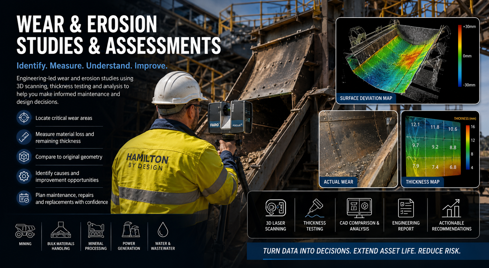
Wear and Erosion Studies and Assessments
Industrial equipment can continue operating while significant wear develops inside chutes, pipes, hoppers, tanks, ducts and other difficult-to-inspect areas. By the time the damage becomes visible, maintenance teams may be dealing with reduced performance, material leakage, damaged liners or an unplanned shutdown.
Hamilton By Design provides engineering-led wear and erosion studies to help identify where material loss is occurring, assess its extent and support practical maintenance, repair and replacement decisions.
Our approach can combine 3D laser scanning, dimensional inspection, thickness measurements, CAD comparison and mechanical engineering analysis. The objective is to turn existing-condition information into usable engineering outcomes.
The Problem with Unmeasured Wear
Maintenance teams may know that an asset is wearing, but they may not know:
- Where the most severe wear is located
- How much material has been lost
- Whether wear is localised or widespread
- Whether a liner is approaching the end of its service life
- Whether the underlying structure has been affected
- Whether the wear rate is increasing
- Which areas should be repaired during the next shutdown
- Whether the original equipment geometry is contributing to the problem
Manual inspections can identify obvious damage, but they may not provide sufficient information to quantify complex surface loss or compare the equipment with its original geometry.
A wear and erosion study provides a structured way to document the asset’s current condition and identify the areas that require further investigation.
What Is a Wear and Erosion Study?
A wear and erosion study investigates the location, extent, pattern and likely causes of material loss from industrial equipment.
Wear can be caused by repeated contact, sliding, impact or abrasion. Erosion is commonly associated with particles, droplets or fluids moving across or striking a surface.
Depending on the asset and operating environment, the study may investigate:
- Abrasive wear caused by bulk materials
- Impact wear at transfer and discharge points
- Sliding wear along chutes and liners
- Erosion caused by particles carried in air, gas or liquid
- Erosion-corrosion in piping and process equipment
- Cavitation damage near pumps and valves
- Corrosion beneath liners or protective coatings
- Fretting or contact wear between moving components
- Deformation caused by uneven material loss
- Reduction in plate, pipe or liner thickness
- Changes in equipment capacity or internal clearances
The study can form part of a broader engineering study and assessment or be completed as a focused investigation of a particular asset.
Who Uses Wear and Erosion Studies?
Wear and erosion studies can support:
- Maintenance managers
- Reliability engineers
- Mechanical engineers
- Asset-integrity engineers
- Shutdown planners
- Fixed-plant supervisors
- Processing-plant managers
- Project engineers
- Maintenance contractors
- Equipment manufacturers
- Fabricators and liner suppliers
The findings can help these teams determine what should be repaired, what should be monitored and what may require redesign.
Where Can Wear and Erosion Studies Be Applied?
Chutes and Transfer Stations
Material transfer systems are frequently exposed to impact, abrasion and sliding wear.
A study may investigate:
- Chute walls
- Impact plates
- Hood and spoon arrangements
- Rock boxes
- Deflector plates
- Dead boxes
- Diverter gates
- Loading zones
- Discharge sections
- Replaceable wear liners
- Skirt systems
- Transfer-point transitions
Where poor material flow contributes to wear, the findings may also support a revised chute and transfer-point design.
Hoppers, Bins and Silos
Hoppers and bins can experience localised wear where material repeatedly impacts or slides across the same surfaces.
Potential problem areas include:
- Hopper transitions
- Discharge openings
- Internal corners
- Flow channels
- Liner joints
- Support interfaces
- High-impact loading zones
- Areas affected by material hang-up
Conveyors and Feed Equipment
Wear studies may be used for:
- Conveyor loading zones
- Apron feeders
- Screw conveyors
- Vibrating feeders
- Belt cleaners
- Conveyor skirts
- Feeder pans
- Discharge pulleys
- Transfer interfaces
Pipes and Slurry Systems
Piping systems may experience concentrated erosion at changes in direction, velocity or cross-sectional area.
Typical inspection areas include:
- Pipe bends
- Elbows
- Tees
- Reducers
- Valves
- Slurry lines
- Pump suction lines
- Pump discharge lines
- Nozzles
- Branch connections
Pumps, Cyclones and Process Equipment
Wear and erosion may affect:
- Pump casings
- Impellers
- Volutes
- Hydrocyclones
- Launders
- Agitators
- Mixing vessels
- Fan blades
- Ductwork
- Dust-extraction equipment
Mobile and Mining Equipment
Wear studies can also support the assessment of:
- Haul-truck trays
- Excavator buckets
- Loader buckets
- Dozer blades
- Dragline components
- Wear plates
- Bucket teeth
- Crusher components
- Mobile equipment liners
Industries We Support
Hamilton By Design can apply wear and erosion studies across:
- Mining
- Coal handling and preparation plants
- Mineral processing
- Quarrying
- Bulk materials handling
- Manufacturing
- Steelmaking
- Smelting
- Water and wastewater
- Power generation
- Food and process manufacturing
- Ports and ship-loading facilities
- Recycling and waste-processing plants
Our broader engineering services are suited to brownfield plants, equipment upgrades, shutdown work and refurbishment projects where existing conditions must be understood before decisions are made.
How Is a Wear and Erosion Study Completed?
1. Define the Operational Problem
The first stage is to understand the equipment, its operating environment and the maintenance concern.
Information reviewed may include:
- Equipment function
- Material being handled
- Material hardness and particle size
- Moisture content
- Flow rate
- Material velocity
- Operating temperature
- Existing liner material
- Original plate thickness
- Maintenance history
- Previous failures
- Replacement frequency
- Available drawings
- Shutdown constraints
This helps determine what information must be captured and which inspection methods are appropriate.
2. Review Existing Information
Available information may include:
- Original equipment drawings
- Manufacturer’s documentation
- Previous inspection reports
- Maintenance photographs
- Earlier thickness measurements
- CAD models
- Liner replacement records
- Failure reports
- Process data
- Previous 3D scans
Existing documentation is assessed to determine whether it accurately represents the asset in its current condition.
3. Inspect and Capture the Existing Condition
The equipment can be inspected using one or more measurement methods.
These may include:
- 3D LiDAR laser scanning
- Handheld 3D scanning
- Ultrasonic thickness testing
- Manual dimensional measurement
- Photography
- Photogrammetry
- Borescope inspection
- Visual inspection
- Drone-based inspection
- Existing-condition survey
Hamilton By Design provides engineering-grade 3D laser scanning to capture plant, equipment and surrounding interfaces as they exist at the time of inspection.
4. Establish the Nominal or Baseline Geometry
To measure wear, the current condition must be compared with an appropriate reference.
The baseline may be established from:
- The original CAD model
- Manufacturer’s drawings
- An unworn replacement component
- A previous 3D scan
- Known original plate thickness
- A symmetrical unworn surface
- A reconstructed nominal surface
- A newly manufactured liner or wear plate
Where drawings are unavailable or unreliable, reverse-engineering methods may be used to reconstruct the nominal geometry.
5. Compare the Existing and Nominal Conditions
The captured condition can be aligned with the baseline to identify dimensional differences.
This comparison may be used to produce:
- Colour-coded deviation maps
- Wear-depth maps
- Cross-sections
- Surface profiles
- Minimum-thickness locations
- Material-loss calculations
- Missing-volume estimates
- Areas of deformation
- Areas requiring further testing
The results allow maintenance teams to see where wear is concentrated rather than relying only on isolated measurements.
6. Investigate the Likely Causes
Identifying wear does not necessarily explain why it is happening.
Possible contributing factors include:
- Direct material impact
- Excessive particle velocity
- Unfavourable impact angle
- Material sliding over unprotected surfaces
- Turbulent flow
- Recirculation
- Material build-up
- Poorly positioned liners
- Gaps between liner plates
- Loose or damaged liners
- Incorrect liner material
- Inadequate liner thickness
- Equipment misalignment
- Changes in process conditions
- Corrosion behind liners
- Localised vibration
- Cavitation
- Poor transfer geometry
For bulk materials-handling equipment, the study may identify opportunities to modify the flow path or improve the chute design.
7. Develop Engineering Recommendations
The study may recommend:
- Immediate repairs
- Localised liner replacement
- Full liner replacement
- Increased liner thickness
- Alternative liner materials
- Replaceable wear panels
- Hardfacing or protective coatings
- Changes to chute geometry
- Revised impact-plate positions
- Improved access for inspection
- Additional thickness-monitoring points
- Changes to maintenance intervals
- Repeat scanning after a defined period
- Further engineering analysis
- Replacement component design
Tools That Can Assist with Wear and Erosion Studies
3D LiDAR Laser Scanning
LiDAR scanning can capture millions of measurement points across large plant areas and equipment surfaces.
It is particularly useful for:
- Large chutes and hoppers
- Transfer stations
- Conveyor interfaces
- Tanks and vessels
- Ductwork
- Plant layouts
- Surrounding structures
- Difficult-to-measure brownfield installations
A scan can also record adjacent structures, pipework, access platforms and equipment interfaces that may affect repair or replacement work.
Learn more about our 3D laser scanning services.
Handheld 3D Scanning
Handheld scanners may be suitable for smaller components or surfaces requiring detailed local capture.
Applications may include:
- Pump casings
- Impellers
- Pipe bends
- Wear plates
- Machine components
- Buckets
- Teeth and cutting edges
- Small chute sections
- Replacement components
Ultrasonic Thickness Testing
Ultrasonic thickness testing can help determine the remaining wall thickness of equipment where access is available from only one side.
Typical applications include:
- Pipes
- Chutes
- Tanks
- Hoppers
- Ductwork
- Platework
- Pressure-containing equipment
Thickness testing can complement 3D scanning because a surface scan records the accessible geometry but does not, by itself, measure the remaining thickness of a closed plate or pipe wall.
CAD and Surface-Comparison Software
Point clouds, meshes and measured surfaces can be compared with CAD geometry using specialist engineering and inspection software.
This can assist with:
- Aligning scan data to CAD
- Producing deviation maps
- Creating cross-sections
- Measuring surface loss
- Calculating missing volume
- Modelling replacement liners
- Reconstructing original geometry
- Preparing repair and fabrication drawings
Hamilton By Design can convert captured geometry into usable CAD data through its reverse-engineering and 3D scanning workflow.
Repeat Scanning and Change Detection
Repeat scanning can help identify how an asset changes over time.
For meaningful comparisons, the scans should be aligned using stable reference geometry or permanent survey targets.
Repeat datasets may help estimate:
- Changes in wear depth
- Changes in material-loss volume
- Progression of localised wear
- Areas of accelerating degradation
- Approximate wear rate
- Likely future repair locations
Wear rates should be treated carefully because operating conditions may change between inspection periods.
Discrete Element Modelling
Discrete element method modelling can simulate how bulk particles move through chutes, hoppers and transfer systems.
DEM may assist in identifying:
- High-impact zones
- Sliding-wear zones
- Particle trajectories
- Material velocities
- Recirculation
- Dead zones
- Uneven material distribution
- Potential geometry improvements
DEM does not replace physical inspection. It can, however, help investigate why particular areas are experiencing repeated wear.
Computational Fluid Dynamics
Computational fluid dynamics may assist where erosion is associated with:
- Slurries
- Liquids
- Gas-borne particles
- Turbulent flow
- High-velocity fluids
- Pipe bends
- Valves
- Cyclones
- Pumps
- Ducts
CFD can help identify high-velocity or turbulent regions that may correspond with field-observed erosion.
Expected Deliverables
The deliverables will depend on the equipment, available information and purpose of the study.
They may include:
- Existing-condition point cloud
- Registered 3D scan data
- Inspection photographs
- Wear-location drawings
- Colour-coded deviation maps
- Ultrasonic thickness map
- Minimum measured thicknesses
- Cross-sections through critical areas
- Surface-profile comparisons
- Estimated material-loss volume
- Comparison with nominal CAD geometry
- Identification of critical wear zones
- Assessment of likely wear mechanisms
- Repair and replacement priorities
- Revised liner designs
- Replacement-component models
- Fabrication drawings
- Recommended monitoring locations
- Proposed repeat-inspection intervals
- Engineering report
Common point-cloud and CAD deliverables may include E57, RCP, RCS, LAS, DWG, DXF, STEP, SAT or native CAD formats, depending on project requirements.
Benefits of a Wear and Erosion Study
A structured study can help maintenance and engineering teams:
- Locate wear before it causes a major failure
- Improve shutdown planning
- Define repair quantities more accurately
- Avoid replacing serviceable areas unnecessarily
- Prioritise critical repairs
- Compare alternative liner arrangements
- Improve replacement-component fit
- Establish a baseline for future inspections
- Reduce reliance on outdated drawings
- Understand whether geometry contributes to wear
- Improve maintenance documentation
- Support asset-life-extension decisions
Engineering-Led Existing-Condition Assessment
Hamilton By Design does more than collect measurement data.
Our approach combines:
- Site inspection
- Engineering-grade reality capture
- Mechanical engineering knowledge
- CAD modelling
- Reverse engineering
- Materials-handling experience
- Fabrication and maintenance understanding
This enables the captured information to be assessed in the context of how the equipment operates, how it is maintained and how it may be repaired or improved.
Our experience includes mining, materials handling, industrial plants, processing facilities and brownfield engineering projects across Australia.
When Should a Wear Study Be Completed?
A wear and erosion study may be appropriate:
- Before a planned shutdown
- Before ordering replacement liners
- After repeated liner failures
- When leakage or breakthrough is suspected
- When equipment performance has declined
- Before refurbishing an asset
- Before modifying a chute or transfer point
- When original drawings are unavailable
- When manual measurements are inconsistent
- After an unexpected failure
- When establishing a long-term monitoring program
- When comparing alternative liner materials
- Before preparing fabrication drawings
Discuss Your Wear or Erosion Problem
The most appropriate study method depends on the equipment, access, operating conditions and decisions that must be made.
Hamilton By Design can help assess the existing condition, identify suitable capture methods and convert the findings into practical maintenance or engineering recommendations.
Contact Hamilton By Design to discuss a wear and erosion study for your plant or equipment.
Frequently Asked Questions
What is the difference between wear and erosion?
Wear is a broad term for the gradual removal or deformation of material caused by contact, sliding, impact, abrasion or repeated movement.
Erosion normally refers to material loss caused by moving particles, droplets or fluids striking or flowing across a surface. Industrial equipment may experience several wear mechanisms at the same time.
Can 3D laser scanning measure equipment wear?
Yes, where the worn surface is visible to the scanner and a suitable reference geometry is available.
The scan can be compared with an original CAD model, an earlier scan, an unworn component or a reconstructed nominal surface. This comparison can show where the surface has changed and how the wear is distributed.
However, laser scanning does not directly measure the remaining thickness of a closed wall. Ultrasonic thickness testing may also be required.
Can wear be measured without original drawings?
Yes. Several methods may be used when original drawings are unavailable.
The baseline may be developed from:
- An unworn replacement component
- A previous scan
- Known plate thicknesses
- A symmetrical unworn area
- Manufacturer’s information
- A reconstructed nominal surface
- Reverse-engineered geometry
The reliability of the comparison will depend on the quality of the available reference.
Can a wear study determine remaining service life?
A single inspection can identify current material loss, but it may not establish a reliable wear rate.
Estimating remaining service life generally requires:
- Known original dimensions
- Repeat measurements
- Stable operating conditions
- Suitable acceptance criteria
- Knowledge of the material
- Understanding of the failure mechanism
Any service-life estimate should account for uncertainty and possible changes in operating conditions.
How often should equipment be scanned?
The inspection interval depends on:
- Severity of wear
- Equipment criticality
- Operating hours
- Material being handled
- Previous wear rate
- Shutdown frequency
- Consequences of failure
- Accessibility
- Existing monitoring data
A heavily worn, safety-critical asset may require more frequent inspections than equipment with stable and predictable wear.
Can scanning be completed during a shutdown?
Yes. Shutdowns often provide the best access to internal chute surfaces, hoppers, tanks, pipes and process equipment.
The equipment normally needs to be:
- Isolated
- Cleaned sufficiently for inspection
- Safe to access
- Free of moving material
- Available for the agreed inspection period
Access and isolation requirements should be reviewed during project planning.
Does the equipment need to be cleaned before scanning?
Generally, yes.
Material build-up, mud, product residue and loose corrosion can obscure the true equipment surface. The required level of cleaning depends on the purpose of the study.
If the objective is to measure plate or liner wear, the underlying surface must normally be visible.
Can scanning identify corrosion behind a liner?
Not directly if the corrosion is hidden behind an installed liner.
Scanning can identify visible deformation, missing liners, gaps or changes in exposed geometry. Hidden corrosion may require liner removal, ultrasonic testing or another nondestructive inspection method.
Can you compare scans taken at different times?
Yes, provided the datasets contain reliable common reference geometry or permanent survey controls.
The scans must be accurately registered before changes are assessed. Movement of the equipment, structures or reference points must also be considered.
Can a wear study help redesign a chute?
Yes.
Where wear is associated with material impact, velocity or poor flow geometry, the findings can support changes such as:
- Repositioned impact plates
- Revised chute angles
- Improved liner coverage
- Replaceable wear panels
- Reduced particle impact
- Improved flow direction
- Alternative liner materials
- Modified hood-and-spoon geometry
Further analysis, including DEM, may be recommended for complex bulk-material flow problems.
What information is needed before providing a proposal?
Useful initial information includes:
- Equipment type
- Site location
- Description of the problem
- Available drawings
- Photographs
- Approximate equipment size
- Access limitations
- Shutdown dates
- Cleaning arrangements
- Required deliverables
- Previous inspection results
- Known liner or plate thickness
- Preferred CAD and point-cloud formats
A site visit or preliminary discussion may be recommended where the required scope is not yet clear.
What file formats can be supplied?
Depending on the project, deliverables may include:
- E57
- RCP
- RCS
- LAS
- DWG
- DXF
- STEP
- SAT
- Parasolid
- SolidWorks files
- PDF drawings
- Inspection reports
- Deviation maps
- Cross-section drawings
The required formats should be agreed before data processing and modelling begin.
Do you provide fabrication drawings for replacement liners?
Yes. Where included in the scope, scan data and engineering measurements can be used to produce:
- Replacement liner models
- Wear-plate layouts
- Cutting profiles
- Fabrication drawings
- Installation drawings
- General arrangements
- Sections and details
- Bills of materials
Additional engineering review may be required where the replacement changes the original equipment design.
Can you inspect operating equipment?
External LiDAR capture may sometimes be completed while surrounding plant remains operational, subject to site access and safety requirements.
Internal wear inspection normally requires the equipment to be isolated, cleaned and made safe for entry. Hot, moving or material-filled equipment may require specialised remote monitoring methods outside the scope of conventional terrestrial scanning.
Is LiDAR scanning accurate enough for a wear study?
LiDAR can be suitable for mapping broad wear patterns and measuring larger equipment surfaces.
The required accuracy depends on:
- Expected wear depth
- Equipment size
- Surface condition
- Scanning distance
- Line of sight
- Scanner type
- Registration method
- Required engineering decision
Small components or shallow wear may require a higher-resolution handheld scanner, ultrasonic testing or precision measurement equipment.
Can a study identify why liners are failing early?
It may help identify likely contributing factors such as:
- Concentrated impact
- Inadequate liner coverage
- Poor liner support
- Gaps between liners
- Incorrect material selection
- Loose fasteners
- Unexpected material trajectories
- Excessive particle velocity
- Changes in feed conditions
- Corrosion behind liners
Laboratory testing, process data or specialist materials advice may also be required before selecting a replacement material.
What areas of Australia does Hamilton By Design support?
Hamilton By Design supports industrial, mining and infrastructure projects across Australia, including Sydney, the Central Coast, Newcastle, the Hunter Valley, Brisbane, Melbourne, Perth and regional mining locations.
Project requirements, travel arrangements and site access can be discussed during the proposal stage.

Contact Us – Talk To Us
Our clients:
























