Fabrication Integrated Modelling (FIM):

Sydney manufacturing workshop using Fabrication Integrated Modelling to connect engineering design, CNC data, and local steel fabrication.

Fabrication Integrated Modelling (FIM): Why Itโ€™s the Future for Local Fabricators

Why It Is the Future for Local Fabricators

The fabrication industry is undergoing a fundamental transformation. Increasing project complexity, tighter tolerances, compressed schedules, labour shortages, and rising material costs are placing unprecedented pressure on fabricators โ€” particularly local workshops operating in competitive markets. At the same time, clients are demanding greater certainty: certainty of fit, certainty of schedule, and certainty of cost.

Traditional fabrication workflows, built around 2D drawings and manual interpretation, are no longer sufficient to meet these expectations. They rely heavily on experience, assumptions, and rework โ€” all of which introduce risk. In this environment, Fabrication Integrated Modelling (FIM) is emerging not as a luxury, but as a necessity.

FIM represents a shift from drawing-based fabrication to model-driven fabrication, where a single, coordinated digital model governs design intent, fabrication detailing, procurement, machining, assembly, and installation. For local fabricators, this shift offers a path to higher productivity, improved margins, and long-term relevance in an evolving industry.


What Is Fabrication Integrated Modelling (FIM)?

Fabrication Integrated Modelling is a methodology where the fabrication model becomes the primary source of truth across the entire project lifecycle. Instead of treating design, drafting, fabrication, and installation as disconnected stages, FIM integrates them into a continuous digital workflow.

In an FIM environment:

  • Engineering intent is embedded directly into the model
  • Fabrication constraints are considered from the outset
  • Quantities, tolerances, and interfaces are defined digitally
  • Fabrication data flows directly to machines and shop documentation
  • Installation sequencing is validated before material is cut

The model is not merely a visual aid โ€” it is a fully informed digital prototype of the fabricated asset.

From Drawings to Data: A Fundamental Shift

Historically, fabrication has relied on 2D drawings as the primary communication tool. These drawings require interpretation by drafters, trades, and supervisors, each introducing assumptions based on experience and context. While this approach has worked for decades, it becomes increasingly fragile as projects grow more complex.

Fabrication Integrated Modelling replaces interpretation with explicit data. Hole locations, weld preparations, connection details, clearances, and tolerances are all defined within the model. This reduces ambiguity and ensures that everyone โ€” from estimator to machine operator โ€” is working from the same information.

The result is a dramatic reduction in errors, clarifications, and rework.


Why FIM Is Gaining Momentum Now

Several industry pressures are accelerating the adoption of FIM:

  • Increasing complexity of industrial and infrastructure projects
  • Reduced tolerance for errors during shutdowns and brownfield upgrades
  • Labour shortages and loss of experienced trades
  • Higher expectations for schedule and cost certainty
  • Growing integration of CNC and automated fabrication equipment

FIM addresses these challenges by improving coordination, predictability, and efficiency at the source โ€” before fabrication begins.


Fabrication Integrated Modelling in a Sydney workshop showing engineers and fabricators using a shared 3D model to drive CNC fabrication and steel assembly.

Key Benefits of Fabrication Integrated Modelling

Reduced Errors and Rework

Rework is one of the most significant drains on fabrication profitability. Errors discovered on the workshop floor or during installation often result in cascading impacts: delays, additional labour, material waste, and strained relationships with clients.

By resolving interfaces, clashes, and tolerances digitally, FIM enables fabricators to identify and eliminate issues before steel is cut. Assemblies are tested virtually, connections are validated, and fit-up risks are significantly reduced.

This proactive approach shifts problem-solving upstream, where changes are faster, cheaper, and less disruptive.


Improved Fabrication Efficiency and Throughput

Fabrication speed is not achieved by rushing work โ€” it is achieved by removing uncertainty. FIM provides clarity on what needs to be fabricated, in what order, and to what tolerance.

Benefits include:

  • Clear fabrication sequencing
  • Reduced downtime waiting for clarifications
  • Better planning of labour and machine utilisation
  • More predictable workshop flow

Local fabricators using FIM often report smoother operations, fewer interruptions, and a higher percentage of โ€œright-first-timeโ€ components.


Better Use of Skilled Labour

Skilled trades are becoming harder to find and retain. Fabrication Integrated Modelling helps maximise the value of skilled workers by giving them better information, not more guesswork.

Fitters receive assemblies that align as expected. Welders focus on quality rather than correcting geometry. Supervisors make decisions based on accurate model data rather than assumptions. Apprentices gain clarity and confidence by working from model-based instructions.

Rather than replacing experience, FIM captures and amplifies it.


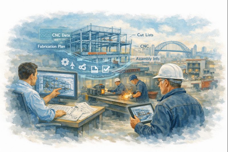
Seamless Integration with CNC and Fabrication Equipment

One of the strongest advantages of FIM is its ability to connect directly with modern fabrication equipment. The same model used for coordination and verification can generate machine-ready data, including:

  • NC files for beam lines and plate processors
  • Cut lists and nesting data
  • Part numbers and assembly marks
  • Machining references

This eliminates duplication of effort and reduces the risk of transcription errors. It also shortens the time between design approval and fabrication start, improving responsiveness to project changes.


Competitive Advantage for Local Fabricators

Local fabricators often compete with offshore suppliers on price alone โ€” a contest that is difficult to win. FIM allows local workshops to compete on value rather than cost.

Key differentiators enabled by FIM include:

  • Faster response to changes
  • Higher confidence in fit-up for complex or brownfield sites
  • Reduced installation risk
  • Stronger collaboration with engineers and constructors

When site conditions change โ€” as they inevitably do โ€” local fabricators using FIM can adapt quickly, update models, and deliver revised components without significant disruption. This agility is a powerful advantage over remote fabrication alternatives.


FIM in Brownfield and Upgrade Projects

Brownfield projects present some of the greatest challenges in fabrication. Existing assets rarely match legacy drawings, and tolerances are often tight. Discovering misalignment during installation can result in costly delays and extended shutdowns.

Fabrication Integrated Modelling, often combined with accurate site capture, allows fabricators to design and fabricate components that align with actual site conditions rather than assumptions.

This approach reduces:

  • On-site modifications
  • Temporary works
  • Installation delays
  • Safety risks associated with forced fit-ups

For local fabricators servicing industrial plants and operational facilities, FIM is rapidly becoming an expected capability.


Financial Benefits: Protecting Margins, Not Just Schedules

While FIM is often associated with speed and accuracy, its most important benefit may be margin protection.

Model-based workflows enable:

  • More accurate pricing through reliable quantities
  • Reduced contingency allowances
  • Predictable labour and machine hours
  • Lower material waste
  • Fewer disputes and variations

By increasing certainty, FIM allows fabricators to price work confidently rather than defensively. Over time, this leads to healthier margins and more sustainable operations.


Earlier Engagement and Better Project Outcomes

Fabricators who adopt FIM often find themselves involved earlier in projects. Engineers and asset owners increasingly recognise the value of fabrication input during design development.

Early collaboration enables:

  • Design for manufacture and assembly
  • Smarter connection strategies
  • Reduced installation complexity
  • Improved safety outcomes

This shifts the fabricatorโ€™s role from reactive supplier to active project partner, strengthening relationships and improving project outcomes for all parties.


Overcoming Barriers to Adoption

Adopting Fabrication Integrated Modelling requires investment โ€” not only in software and systems, but in people and processes. Common challenges include:

  • Training requirements
  • Changes to established workflows
  • Initial productivity adjustments
  • Cultural resistance to new methods

Successful fabricators address these challenges incrementally. They start with pilot projects, focus on repeatable wins, and work closely with engineering and modelling partners to build capability over time.

The risk of maintaining outdated workflows is increasingly greater than the risk of change.


The Future of Fabrication: Integrated Digital Ecosystems

FIM is not the final destination โ€” it is the foundation for a more connected fabrication industry. As digital maturity increases, fabrication models will increasingly link to:

  • Digital twins
  • Quality assurance records
  • Traceability and compliance systems
  • Asset management platforms
  • Automated inspection and verification

In this future, the fabrication model becomes a long-term asset, supporting not only construction but operation and maintenance.


Why Fabrication Integrated Modelling Is the Future for Local Fabricators

Local fabrication is not disappearing โ€” it is evolving. Workshops that continue to rely solely on 2D drawings and manual processes will face increasing pressure from cost, risk, and competition. Those that embrace Fabrication Integrated Modelling will position themselves for long-term success.

By adopting FIM, local fabricators can:

  • Deliver higher quality with greater confidence
  • Reduce rework and wasted effort
  • Protect margins in competitive markets
  • Strengthen relationships with engineers and clients
  • Build resilient, future-ready businesses

Fabrication Integrated Modelling is not about replacing trades or experience. It is about supporting them with better information, clearer intent, and integrated workflows.

For local fabricators willing to invest in capability and collaboration, FIM is not just the future โ€” it is the pathway to remaining relevant, competitive, and profitable in an increasingly digital industry.

Name
Would you like us to arrange a phone consultation for you?
Address

How AS 1100 and LiDAR Scanning Work Together: From Point Cloud to Compliant Drawings

Graduate engineer and senior engineer using LiDAR scanning on a Parramatta River construction site, reviewing point cloud data for accurate design.

AS 1100 & LiDAR Scanning: Compliant Engineering Drawings from Point Clouds

If youโ€™ve ever tried to update old plant drawings, verify a brownfield tie-in, or issue โ€œas-builtโ€ documentation after a shutdown, youโ€™ll know the pain: the site never matches the drawings, access is limited, and the smallest dimensional miss can cascade into rework, clashes, and schedule blowouts.

Thatโ€™s where engineering-grade LiDAR scanning and AS 1100 (the Australian Standard for technical drawing) make a powerful combination. LiDAR gives you truth data (reality capture), and AS 1100 gives you a shared language for turning that truth into clear, consistent, contract-ready documentation.

At Hamilton By Design, we treat scanning and drawing as one joined workflow: capture accurately โ†’ model intelligently โ†’ document to AS 1100 so everyone downstream can build, fabricate, install, and sign off with confidence.
(If you want to see the service side of this workflow, start here: https://www.hamiltonbydesign.com.au/home/engineering-services/3d-laser-scanning/3d-laser-scanning-for-engineering-projects/ and here: https://www.hamiltonbydesign.com.au/home/3d-lidar-scanning-digital-quality-assurance/)


What AS 1100 actually โ€œdoesโ€ in the real world

AS 1100 standardises the way we communicate engineering information through drawings: layout, line types, projection methods, dimensioning rules, tolerancing conventions, symbols, notes, and drawing presentation.

In practice, AS 1100 helps you answer questions like:

  • Which edges are visible vs hidden? (line conventions)
  • How are views arranged and interpreted? (projection and view layout)
  • How do we dimension so the fabricator canโ€™t misread it? (dimensioning rules)
  • How do we document what matters vs whatโ€™s โ€œreference onlyโ€? (notes and drawing hierarchy)
  • How do we keep drawing sets consistent across multiple contributors? (formatting + standards)

That consistency is exactly whatโ€™s needed after a scanโ€”because point clouds are rich, but theyโ€™re not automatically โ€œcommunicableโ€ in the way a compliant drawing set is.


What LiDAR scanning adds that drawings alone canโ€™t

A LiDAR scanner captures millions (often billions) of spatial points that represent real surfacesโ€”steel, concrete, pipe, equipment, structureโ€”creating a point cloud that can be registered into a unified coordinate system.

Dassault Systรจmes SolidWorks Professional Weldments certification badge

In the engineering context, the big advantages are:

  • Speed: capture complex geometry quickly, often with minimal disruption
  • Coverage: see whatโ€™s hard to measure with tape/total station (overhead services, congested pipe racks, odd geometry)
  • Context: capture โ€œeverything,โ€ not just what someone remembered to measure
  • Traceability: you can always โ€œgo backโ€ to the scan for verification and queries
  • Clash prevention: scan-to-CAD makes it far easier to design upgrades that actually fit

But hereโ€™s the key: a point cloud isnโ€™t a deliverable most trades can fabricate from directly.
Thatโ€™s why AS 1100 becomes the bridge between capture and construction.


The combined workflow: Point cloud โ†’ model โ†’ AS 1100 drawings

1) Capture the site as it really is

We scan the area of interest and register scans into a coordinated dataset. This becomes the base truth for everything that follows. If the project is shutdown-driven, we plan scanning around access windows and risk controls (often capturing adjacent tie-in zones too, because โ€œnearbyโ€ services are where surprises live).

2) Establish intent: โ€œWhat are we delivering?โ€

Not every project needs the same output. Typical outcomes include:

  • As-built drawings for existing assets
  • As-found models to support new design work
  • Dimensional verification for fit-up and prefabrication
  • Digital QA against design intent (scan-vs-model comparison)

Hamilton By Design leans hard into this QA piece where it matters mostโ€”because catching a misalignment early is cheaper than discovering it on install day.
More on the QA angle here: https://www.hamiltonbydesign.com.au/home/3d-lidar-scanning-digital-quality-assurance/

3) Convert scan data into engineering geometry (as much as needed)

Sometimes the best output is a controlled 3D model (plant layout, pipe spools, structural members). Other times the project is best served by 2D drawings extracted from a model.

Weโ€™ll typically create:

  • key datums and grids
  • primary steel / structure
  • equipment envelopes and critical interfaces
  • piping runs and connection points (where relevant)
  • floor levels, platforms, access constraints, clearance zones

4) Document to AS 1100 so the drawing set is unambiguous

This is where AS 1100 shines. We turn geometry into drawings that read cleanly and consistently across teams.

That includes:

  • correct view layouts (plan/elevation/section/detail)
  • line conventions (visible/hidden/centre lines)
  • clear dimensioning strategy (functional dims first)
  • consistent annotation and notes
  • drawing borders, title blocks, revision control, and drawing register discipline

In short: LiDAR gives accuracy, AS 1100 gives clarity.


Where AS 1100 + LiDAR scanning delivers immediate value

Brownfield upgrades and tie-ins

Tie-ins fail when the โ€œas-builtโ€ condition is wrong. A scan gives you real geometry; AS 1100 drawings package it so designers, fabricators, and installers share the same reference. This is especially useful when multiple contractors are interfacing.

Fabrication and spool accuracy

If youโ€™re fabricating offsite (pipe spools, platform steel, handrail sections, ducting), you need dependable dimensions and an agreed drawing language. Scan-derived models support accuracy; AS 1100 drawings support fabrication interpretation and QA sign-off.

Shutdown planning and constructability

A point cloud is a brilliant planning toolโ€”access routes, crane clearances, removal paths, temporary works, and โ€œwhatโ€™s in the way.โ€ But shutdown packages still need compliant drawings for permits, isolations, install workpacks, and handover packs. AS 1100 keeps those packages readable and defensible.

Verification and โ€œwhat changed?โ€

Sites evolve. A scan provides a timestamped snapshot. Drawings updated to AS 1100 become the controlled record: what was there, what was installed, and what the current state is. That matters for maintenance, safety, and future projects.


Practical example: Turning a congested pipe rack into a buildable upgrade

Imagine youโ€™re adding a new line through an existing pipe rack:

  1. Scan the rack to capture all existing services, supports, cable trays, and steel
  2. Model critical geometry (existing plus proposed) to check routing and supports
  3. Clash check before fabrication begins
  4. Issue AS 1100 drawings for:
    • support details
    • spool isometrics (if applicable)
    • arrangement drawings showing tie-in locations
    • sections through congestion zones
    • installation notes and tolerances where appropriate
  5. Verify post-install with a follow-up scan if required for QA/closeout

Thatโ€™s the โ€œwork togetherโ€ part: the scan stops guesswork, and AS 1100 stops misinterpretation.


Common mistakes when scanning isnโ€™t tied back to AS 1100

  • Delivering point clouds without a drawing strategy (stakeholders canโ€™t use them effectively)
  • Over-modelling everything (time is spent modelling non-critical items instead of delivering useful documentation)
  • Unclear dimensioning (scan accuracy is wasted if dimensions are presented ambiguously)
  • No controlled datums (people argue about โ€œwhere zero isโ€ and models drift between disciplines)
  • Weak revision control (the drawing set becomes untrustworthy fast)

A standards-led drawing approach prevents most of these.


How we approach it at Hamilton By Design

Our angle is simple: engineering-led scanningโ€”not scanning for its own sake.

  • We capture reality with LiDAR.
  • We translate it into the level of model detail the project actually needs.
  • We document outputs with the discipline and consistency expected in Australian engineering environments.

If you want the practical breakdown of how we do scan capture and modelling for projects, start here:
https://www.hamiltonbydesign.com.au/home/engineering-services/3d-laser-scanning/3d-laser-scanning-for-engineering-projects/

And if your priority is dimensional verification, fit-up confidence, or proving compliance against design intent, this page explains our digital QA approach:
https://www.hamiltonbydesign.com.au/home/3d-lidar-scanning-digital-quality-assurance/


Hamilton By Design logo displayed on a blue tilted rectangle with a grey gradient background

Closing thought: accuracy is only valuable if itโ€™s understandable

LiDAR scanning can deliver millimetre-grade spatial truth. But in real projects, truth still has to travel through peopleโ€”engineers, drafters, fabricators, installers, supervisors, and asset owners.

AS 1100 makes that truth readable.
LiDAR makes it reliable.

Together, they turn messy real-world geometry into clear, controlled documentation that supports safer installs, faster shutdowns, and fewer surprises.

Name
Would you like us to arrange a phone consultation for you?
Address

Engineering-Led 3D Laser Scanning for Industrial Facilities in Sydney

Mechanical engineer and client reviewing construction drawings beside a LiDAR scanner at a Western Sydney construction site with Sydney Olympic Park and Parramatta skyline in the background

Mechanical engineer reverse engineering industrial equipment using 3D LiDAR scanning beside Sydney Harbour

Engineering-Led 3D Laser Scanning for Industrial Facilities in Sydney

In complex industrial environments, accurate site data is critical โ€” but point clouds alone do not solve engineering problems.

At Hamilton By Design, we provide engineering-led 3D laser scanning services across Sydneyโ€™s industrial precincts, delivering not just accurate capture, but build-ready CAD models, verified layouts, and engineering support for plant upgrades, shutdown works, and fabrication projects.

From manufacturing facilities and bulk materials handling plants to port infrastructure and brownfield industrial sites, our scanning workflows are designed to reduce rework, improve constructability, and support safe, compliant engineering outcomes.


Why Engineering-Led Scanning Matters in Industrial Environments

Industrial facilities are rarely documented accurately. Over years of modifications, shutdown changes, and emergency repairs, original drawings quickly become unreliable.

Common issues we see on Sydney industrial sites include:

  • undocumented structural changes
  • misaligned conveyors and transfer points
  • access platforms not matching compliance drawings
  • equipment upgrades that donโ€™t fit as expected
  • safety risks during shutdown installation

Traditional survey-only scanning provides geometry โ€” but without engineering interpretation, design risk remains high.

Hamilton By Design integrates engineering verification directly into the scanning and modelling workflow, ensuring captured data supports:

  • mechanical design
  • structural verification
  • fabrication detailing
  • construction planning

This approach is critical for brownfield upgrades and safety-critical installations.


From Point Cloud to Build-Ready CAD โ€” Not Just Visual Models

Our Sydney scanning projects are delivered as part of a complete scan-to-engineering workflow, including:

  • high-accuracy terrestrial LiDAR scanning
  • registered point cloud datasets
  • engineering-grade CAD and BIM modelling
  • mechanical and structural integration
  • fabrication and construction-ready outputs

This allows project teams to move directly from:

Site capture โ†’ engineering design โ†’ fabrication โ†’ installation

without the delays and risks associated with re-measuring or redesigning due to site conflicts.

For shutdown and live-plant environments, this dramatically reduces:

  • installation clashes
  • hot-work exposure
  • crane and access planning errors
  • schedule overruns

Industrial Facilities We Support Across Sydney

Hamilton By Design provides industrial scanning and engineering support across:

  • manufacturing plants
  • materials handling facilities
  • recycling and processing plants
  • port and logistics infrastructure
  • food and beverage production
  • utilities and treatment facilities

Our team understands the constraints of:

  • live plant operations
  • confined access
  • safety compliance requirements
  • short shutdown windows

Scanning is planned to integrate with plant operations and maintenance teams, not disrupt them.


Sydney Industrial Precincts We Regularly Support

We provide 3D laser scanning and engineering modelling across key industrial areas including:

  • Alexandria and Inner South industrial zones
  • Port Botany and logistics precincts
  • Western Sydney manufacturing corridors
  • North Shore infrastructure and access-restricted sites
  • Regional NSW industrial and mining-linked facilities

Each location presents different engineering challenges โ€” from heavy materials handling to structural access compliance โ€” which is why engineering involvement during scanning is critical.


Supporting Engineering, Fabrication and Compliance

Unlike scanning companies that deliver only spatial data, Hamilton By Design integrates scanning into broader project delivery, supporting:

  • mechanical upgrades and replacements
  • structural strengthening and access platforms
  • conveyor and chute modifications
  • guardrail and walkway compliance upgrades
  • fabrication shop detailing
  • as-built documentation for asset registers

This ensures scanning outputs are aligned with:

  • Australian Standards
  • engineering design requirements
  • construction tolerances

Not just visual representation.


Why Industrial Clients Choose Hamilton By Design

Industrial clients across Sydney engage Hamilton By Design because we offer:

  • โœ” engineer-led scanning and modelling workflows
  • โœ” mechanical and structural design capability in-house
  • โœ” fabrication-aware CAD modelling
  • โœ” experience in mining and heavy industry environments
  • โœ” practical understanding of shutdown and brownfield projects

This allows us to support projects from initial site verification through to construction and commissioning.


When to Use Engineering-Led 3D Scanning

Our Sydney industrial scanning services are particularly valuable for:

  • brownfield plant upgrades
  • conveyor and materials handling modifications
  • access and safety compliance projects
  • clash detection before fabrication
  • replacement of undocumented equipment
  • retrofit installations in congested areas

If the project requires accurate geometry and engineering accountability, scanning must be part of the engineering workflow โ€” not separate from it.


Hamilton By Design logo displayed on a blue tilted rectangle with a grey gradient background

Talk to an Engineering-Led Scanning Team in Sydney

If you are planning an industrial upgrade, shutdown modification, or facility redevelopment in Sydney, Hamilton By Design can provide:

  • engineering-led LiDAR scanning
  • point cloud to CAD modelling
  • mechanical and structural design support
  • fabrication-ready documentation

Contact our team to discuss how engineering-driven site capture can reduce project risk and improve construction outcomes.

Name
Would you like us to arrange a phone consultation for you?
Address

3D Laser Scanning in Kirribilli NSW โ€“ Engineering-Grade Reality Capture for Harbour-Side Projects

Engineer using a LiDAR scanner to capture a Sydney harbour-front residential property with Sydney Harbour Bridge in the background

3D Laser Scanning in Kirribilli NSW โ€“ Engineering-Grade Reality Capture for Harbour-Side Projects


Harbour-side buildings and infrastructure present unique challenges for refurbishment, compliance and upgrade works. Tight access, ageing structures and complex services make accurate site data critical before design or construction begins.

Hamilton By Design provides engineering-grade 3D laser scanning and LiDAR services in Kirribilli and across Sydneyโ€™s Lower North Shore, delivering accurate point cloud data that supports safe, buildable and cost-effective engineering outcomes.


Why 3D Scanning Is Critical in Kirribilli and Harbour Precincts

Kirribilli is characterised by:

  • heritage and character buildings
  • dense strata developments
  • limited access for survey and construction
  • proximity to critical transport and harbour infrastructure

Traditional measurement methods are often inadequate for:

  • structural modifications
  • mechanical plant upgrades
  • access compliance works
  • fabrication-ready design

3D laser scanning captures millions of accurate spatial data points, creating a true digital record of existing conditions before design begins โ€” reducing rework, RFIs and site clashes.


From Point Cloud to Build-Ready CAD and BIM Models

Our service does not stop at site capture.

We convert scan data into:

  • engineering CAD models
  • fabrication drawings
  • BIM-compatible geometry
  • detailed as-built documentation

This supports downstream workflows such as:

  • steel fabrication
  • mechanical installation
  • access system upgrades (AS 1657)
  • structural strengthening designs

Deliverables are tailored to suit engineers, architects and construction teams โ€” not just visualisation.


Typical Applications in Kirribilli and the Lower North Shore

3D scanning is commonly used for:

  • strata refurbishments and upgrades
  • heritage faรงade documentation
  • lift and stair compliance modifications
  • plant room reconfiguration
  • services routing and clash detection
  • harbour-adjacent infrastructure assessments

Because scanning is non-contact and fast to deploy, it allows data capture in occupied buildings with minimal disruption to residents and businesses.


Engineering-Led Scanning โ€” Not Just Survey Output

Hamilton By Design is an engineering-led consultancy, not just a scanning provider.

This means:

  • scan planning is driven by design requirements
  • critical interfaces are prioritised
  • modelling supports fabrication and construction
  • risk is addressed early in the project lifecycle

This approach is particularly valuable in brownfield and retrofit environments where unknown conditions often drive cost overruns.


An engineer reviews detailed structural steel drawings at a drafting table while an engineering-grade LiDAR scan captures an existing waterfront structure in Sydney, illustrating data-driven structural drafting based on accurate as-built conditions.

Servicing Kirribilli, North Sydney and Sydney Harbour Precincts

We regularly support projects across:

  • Kirribilli
  • Milsons Point
  • North Sydney
  • Neutral Bay
  • Chatswood
  • Sydney CBD

And integrate scanning with mechanical, structural and drafting services where required.

Whether the project involves refurbishment, compliance or asset documentation, accurate reality capture forms the foundation for reliable engineering decisions.


Supporting Safe Design and Risk Reduction

Accurate site data enables:

  • early hazard identification
  • better access system design
  • improved constructability reviews
  • reduced site modifications during shutdowns

This aligns with Safe Design principles and reduces downstream safety and scheduling risks.


Talk to Us About 3D Scanning in Kirribilli

If youโ€™re planning refurbishment, compliance upgrades or engineering works in Kirribilli or across Sydneyโ€™s harbour precincts, engineering-grade 3D scanning can eliminate costly unknowns before construction begins.

Contact Hamilton By Design to discuss site capture, modelling and design support for your project.