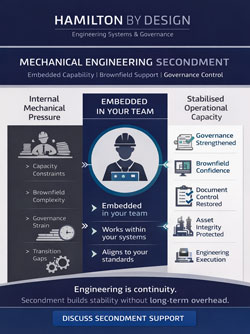
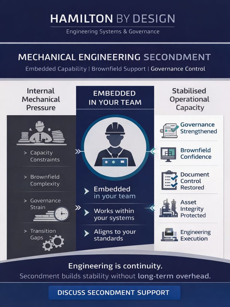
Engineering Secondment for Mechanical Teams
Mechanical engineering teams today operate under sustained pressure.
- Shutdown windows are tighter
- Brownfield modifications are constant
- Documentation is often incomplete
- Internal engineering resources are stretched
- Capital approval cycles are slow
In this environment, hiring permanent staff is not always the right answer.
A structured engineering secondment provides capability, continuity, and control — without increasing long-term overhead.
At Hamilton By Design, secondment is not labour hire.
It is embedded technical capability.
What Is Engineering Secondment?
Engineering secondment is the temporary placement of an experienced engineering professional into your organisation to operate as part of your internal team.
Unlike traditional consulting:
- The engineer works within your systems
- Aligns with your standards
- Supports your projects directly
- Reports within your governance structure
The objective is not to deliver a report and leave.
It is to strengthen your mechanical function during periods of load, transition, or change.
When Mechanical Teams Benefit Most
Secondment is particularly effective when:
- A senior engineer has resigned or is on leave
- A capital upgrade program has accelerated
- Shutdown preparation requires additional oversight
- Brownfield redesign is underway
- Drawing governance needs to be stabilised
- A 3D scanning and digital validation program is commencing
Instead of recruiting under pressure, secondment provides immediate capability.
1️⃣ Stability During Engineering Transitions
Mechanical departments often rely heavily on a small number of experienced engineers.
When one leaves, knowledge gaps appear:
- Historical plant decisions
- Modification records
- Informal workarounds
- Vendor relationships
A seconded engineer with brownfield experience can:
- Maintain continuity
- Support decision-making
- Preserve governance
- Prevent reactive engineering
This reduces operational risk during transition periods.
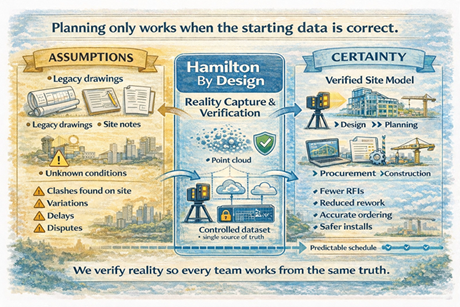
2️⃣ Controlled Support During Brownfield Upgrades
Brownfield engineering is rarely straightforward.
Existing conditions rarely match legacy drawings.
Interfaces are complex.
Shutdown timeframes are unforgiving.
A seconded engineer can:
- Review site conditions alongside your team
- Validate geometry through 3D scanning integration
- Support constructability reviews
- Manage drawing revisions and change control
This is especially valuable when your permanent team is already operating at full capacity.
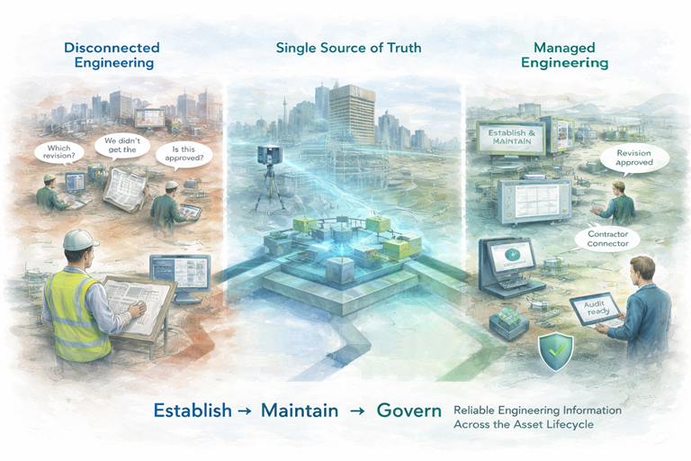
3️⃣ Strengthening Governance Without Growing Headcount
Many mechanical teams struggle with:
- Drawing revision control
- Asset record updates
- Contractor data management
- Change management tracking
- Audit readiness
These responsibilities are critical — but often under-resourced.
Secondment allows you to:
- Embed structured engineering oversight
- Improve documentation discipline
- Align digital records with physical assets
- Stabilise internal processes
All without committing to permanent salary overhead.
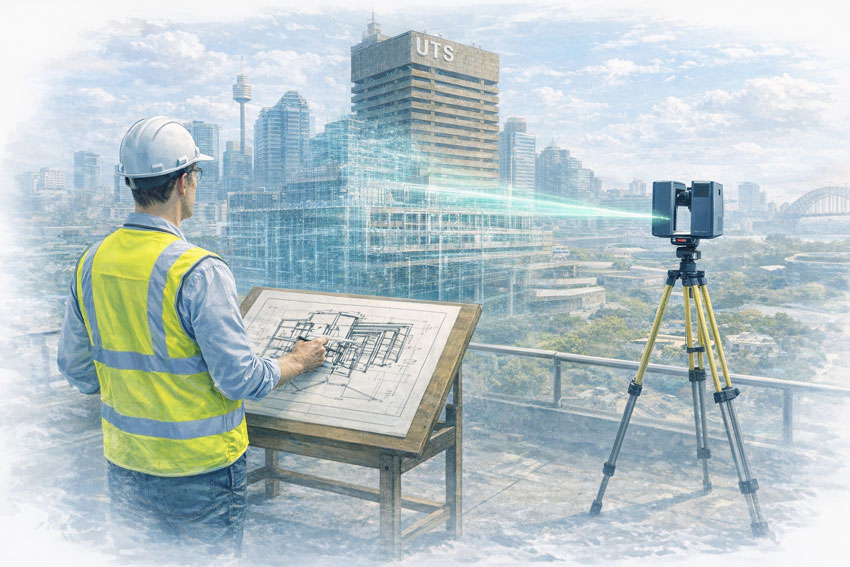
4️⃣ Integration With Digital Validation & 3D Capture
Hamilton By Design integrates secondment with:
- 3D Faro scanning capability
- Digital model validation
- Controlled data environments
- Brownfield geometry verification
A seconded engineer who understands both mechanical systems and digital validation ensures that:
- Design intent matches site conditions
- Documentation remains current
- Future modifications start from verified data
This creates long-term engineering value beyond the immediate assignment.
Secondment vs Consulting vs Labour Hire
| Model | Outcome | Limitation |
|---|---|---|
| Consulting | Advice & deliverables | Limited internal integration |
| Labour Hire | Short-term manpower | Limited governance structure |
| Secondment | Embedded engineering capability | Requires structured scope |
Secondment sits between permanent recruitment and external consultancy — providing practical integration with strategic oversight.
The Hamilton By Design Approach
Our secondment model focuses on:
- Mechanical systems understanding
- Brownfield engineering discipline
- Governance and drawing control
- Shutdown planning support
- Digital validation integration
- Asset stewardship
We operate as an extension of your mechanical team — not as an external observer.
Engineering Is Capacity + Control
Mechanical engineering is not only about solving problems.
It is about maintaining system integrity over time.
Secondment provides:
- Capacity when workload spikes
- Control when governance weakens
- Continuity during transition
- Confidence before capital decisions
For mechanical engineering managers, it is often the most balanced solution between growth and risk.

Hamilton By Design
Supporting mechanical engineers across Australia through structured secondment, digital validation, and engineering governance.