Mechanical Engineering | 3D Scanning | 3D Modelling
Category: Engineering Structural
Structural Engineering focuses on ensuring that structures are safe, stable, and fit for purpose throughout their working life.
This category covers how structural engineering is applied to steelwork, platforms, walkways, foundations, frames, and supporting structures across industrial, mining, power, and building & construction environments. Articles explain how engineers assess loads, connections, materials, and existing conditions to support upgrades, modifications, and new works.
Structural Engineering: Turning Structural Concepts into Buildable, Compliant Outcomes
Structural engineering plays a critical role in ensuring that structures are safe, stable, and fit for purpose—not just on paper, but in the real world.
Across industrial facilities, mining sites, power infrastructure, and building projects, structural engineering is what turns concepts into buildable, verifiable outcomes. It requires more than calculations alone; it depends on accurate information, sound judgement, and clear documentation that can be understood and constructed on site.
At Hamilton By Design, structural engineering is delivered with a strong focus on existing conditions, constructability, and compliance, particularly for brownfield and live environments.
What structural engineering actually delivers
Structural engineering involves the assessment, design, and verification of structures that support loads safely over their intended life.
Typical applications include:
Structural steelwork and framing
Platforms, walkways, stairs, and access systems
Equipment support structures and foundations
Modifications to existing buildings and industrial assets
Strengthening, repair, and upgrade works
In many projects, especially upgrades and refurbishments, the challenge is not designing something new—but understanding what already exists and how it behaves.
Our clients:
Structural engineering on existing and brownfield sites
Many industrial and construction projects rely on incomplete or outdated drawings. Over time, assets are modified, reinforced, or repaired without full documentation, increasing risk when new works are planned.
Structural engineering in these environments often involves:
Verifying existing steel sizes and connections
Assessing capacity against current load requirements
Identifying undocumented changes or deterioration
Designing upgrades that integrate with existing structures
Accurate engineering input at this stage reduces rework, improves safety, and avoids costly site changes during construction.
The role of structural drafting in successful outcomes
Even the best structural design can fail if it is not clearly documented.
Structural drafting is the critical link between engineering intent and construction reality. It translates structural engineering decisions into clear, coordinated drawings that fabricators and builders can rely on.
Well-executed structural drafting ensures:
Load paths and connections are clearly communicated
Member sizes, levels, and interfaces are unambiguous
Drawings reflect actual site conditions
Fabrication and installation can proceed with confidence
Mechanical engineering has always been a balance between creativity and certainty. Every bracket, frame, chute, or structural support we design must perform under real loads, temperatures, and conditions — often in environments where failure simply isn’t an option.
That’s where Finite Element Analysis (FEA) earns its place as one of the most powerful tools in modern design. It allows engineers to move from assumption to verification — transforming the way we predict, test, and optimise mechanical systems.
What Is FEA — and Why It Matters
FEA divides complex geometry into a network of small, interconnected elements. By solving the physical equations that govern stress, strain, and displacement across those elements, engineers can predict how a structure behaves under load, vibration, or temperature.
Instead of relying solely on hand calculations or over-built safety factors, FEA provides quantitative insight into performance — letting us see where structures flex, where stress concentrates, and how design choices affect real-world outcomes.
In mechanical engineering, that means fewer prototypes, lower material costs, and far greater design confidence.
1. Static Analysis — The Foundation of Structural Validation
Static linear analysis is the foundation of most FEA work. It evaluates how a structure responds to steady, time-independent loads such as gravity, pressure, or fixed equipment weight.
Through static analysis, engineers can:
Visualise stress and displacement distribution across a part or assembly.
Evaluate safety factors under different loading conditions.
Check stiffness and material utilisation before fabrication.
Identify weak points or stress concentrations early in design.
This baseline validation is the difference between a design that “should” work and one that will.
2. Assembly-Level Simulation — Seeing the Whole System
Few machines fail because a single part breaks. Most failures happen when components interact under load — bolts shear, brackets twist, or welds experience unplanned tension.
FEA allows engineers to simulate entire assemblies, including:
Contact between parts (bonded, sliding, or frictional).
Realistic boundary conditions such as bearings, springs, or pinned joints.
The influence of welds, fasteners, or gaskets on overall performance.
This system-level view helps mechanical engineers design not only for strength, but also for compatibility and reliability across the full structure.
3. Mesh Control — Accuracy Where It Counts
A simulation is only as good as its mesh. By controlling element size and density, engineers can capture critical detail in stress-sensitive regions like fillets, bolt holes, and weld toes.
Modern FEA tools use adaptive meshing — refining the model automatically in areas of high stress until the solution converges. That means precise, efficient results without excessive computation time.
4. Thermal-Structural Interaction — When Heat Becomes a Load
Many mechanical systems face thermal as well as mechanical challenges. Whether it’s ducting in a process plant or hoppers near heat sources, temperature gradients can cause expansion, distortion, or thermal stress.
FEA allows engineers to:
Model steady-state or transient heat transfer through solids.
Apply convection, radiation, or temperature boundary conditions.
Combine thermal and structural analyses to study thermal expansion and thermal fatigue.
Understanding how heat and load combine helps ensure equipment remains stable, safe, and accurate throughout its lifecycle.
5. Modal and Buckling Analysis — Designing Against Instability
Some risks are invisible until they’re simulated. Vibration and buckling are two of the most overlooked — yet most common — causes of structural failure.
Modal Analysis
Determines a structure’s natural frequencies and mode shapes, helping designers avoid resonance with operating machinery, fans, or conveyors.
Buckling Analysis
Predicts the critical load at which slender members or thin-walled panels lose stability — allowing engineers to reinforce and optimise designs early.
By identifying these limits before fabrication, engineers can prevent problems that are expensive and dangerous to discover on site.
Design Optimisation — Smarter, Lighter, Stronger
Good design is rarely about adding material; it’s about using it wisely. FEA supports parametric and goal-based optimisation, enabling engineers to vary geometry, thickness, or material and automatically test multiple configurations.
You can set objectives such as:
Minimising weight while maintaining strength.
Reducing deflection under fixed loads.
Optimising gusset or flange size for stiffness.
This process of “digital lightweighting” drives better performance and cost efficiency — especially valuable in industries where both material and downtime are expensive.
7. Communication and Confidence
FEA isn’t only a calculation tool — it’s a communication tool. Colour-coded plots, animations, and automated reports make it easier to explain complex mechanical behaviour to project managers, clients, or certifying bodies.
Clear visuals turn stress distributions and displacement fields into a shared language — helping stakeholders understand why certain design choices are made.
Real-World Applications Across Mechanical Engineering
Application
Type of Analysis
Key Benefit
Chutes & Hoppers
Static + Buckling
Confirm wall thickness and frame design for structural load and vibration
Conveyor Frames
Modal + Static
Avoid resonance and ensure adequate stiffness
Pressure Equipment
Thermal + Static
Evaluate thermal stress and hoop stress under load
Machine Brackets
Static + Optimisation
Reduce weight while maintaining rigidity
Platforms & Guarding
Buckling
Validate stability under safety loading
Welded Frames & Supports
Static
Check deformation, stress, and weld performance
These examples show how FEA becomes an everyday design partner — embedded in the workflow of mechanical engineers across manufacturing, resources, and infrastructure.
The Engineer’s Advantage: Data Over Assumption
In traditional design, engineers often relied on prototypes and conservative safety factors. Today, simulation delivers the same assurance — without the waste.
By applying FEA early in the design cycle, mechanical engineers can:
Predict failure modes before they occur.
Shorten development time.
Reduce material usage.
Justify design decisions with quantitative proof.
FEA enables engineers to focus less on guesswork and more on innovation — designing structures that are both efficient and dependable.
Engineering Integrity in Practice
At Hamilton By Design, we integrate FEA into every stage of mechanical design and development. It’s how we ensure that every frame, chute, and mechanical system we deliver performs as intended — safely, efficiently, and reliably.
We use FEA not just to find the limits of materials, but to push the boundaries of design quality — delivering engineering solutions that last in the toughest industrial environments.
Design backed by data isn’t a slogan — it’s how we engineer confidence.
Building a Culture of Verified Design
When FEA becomes part of everyday engineering culture, it changes how teams think. Designers begin to see structures not just as drawings, but as living systems under real forces.
That shift builds trust — between engineer and client, between concept and reality. It’s what defines the future of mechanical design: informed, optimised, and proven before the first bolt is tightened.
In 2024, SafeWork SA concluded a landmark case involving a spectator-roof collapse during a football club redevelopment project in South Australia. While no life-threatening injuries occurred, the incident highlighted how critical it is for design, review, and certification processes to work together to ensure safety on site.
This was the first successful design-related prosecution under South Australia’s Work Health and Safety Act, sending a clear signal to the engineering and construction sector: design decisions carry legal and safety obligations, not just technical ones.
What Happened (Briefly)
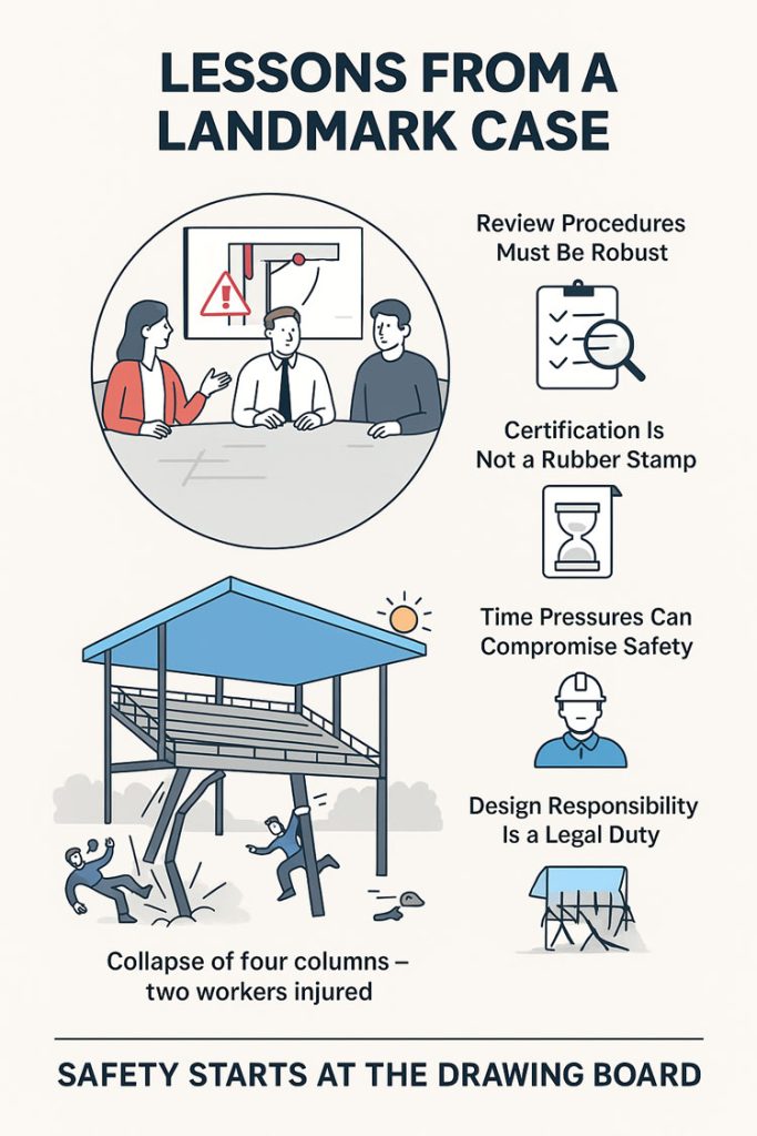
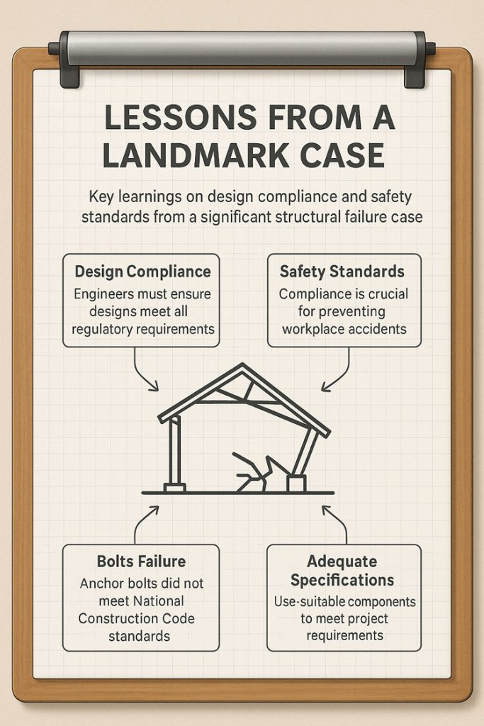
During roof sheeting works in late 2021, four of seven supporting columns of a cantilevered spectator roof failed, causing two apprentices to slide down the roof sheets. SafeWork SA’s investigation found that the anchor bolts specified for the column base plates were inadequate and did not meet the requirements of the National Construction Code (NCC).
An independent compliance review also failed to detect this issue, allowing the error to pass unchecked into construction. The result was a collapse that could have had far more severe consequences had the roof been fully loaded or occupied.
Key Learnings for the Industry
This case underscores several important lessons for engineers, designers, project managers, and certifiers:
1. Design Responsibility Is a WHS Duty
Under the WHS Act, designers have a duty to ensure their work is safe not just in its intended use, but during construction. This means bolts, connections, and base plates must be designed for real-world loads — including wind uplift, combined shear and tension, and concrete breakout limits per NCC and relevant Australian Standards.
2. Review Procedures Must Be Robust — and Followed
Having a documented review procedure is not enough if it isn’t rigorously applied. Independent verification and internal peer review are critical to catching design errors before they reach site.
3. Certification Is Not a Rubber Stamp
Independent certifiers play a key role in safeguarding public safety. They must actively verify that designs meet compliance, rather than simply sign off on documentation.
4. Time Pressures Can Compromise Safety
Compressed project timelines were noted as a factor in missed opportunities to catch the error. Project teams must resist the temptation to shortcut review steps when schedules are tight — safety must remain non-negotiable.
5. Documentation & Traceability Protect Everyone
Maintaining calculation records, checklists, and review signoffs creates a clear audit trail. This helps demonstrate due diligence if something goes wrong.
Why This Matters
The collapse at Angaston Football Club was a relatively small incident with minor injuries — but it could easily have been catastrophic. By learning from cases like this, the industry can improve its processes and prevent future failures.
As professionals, our role is to design for safety, verify rigorously, and document clearly. Doing so protects workers, end-users, and our own organisations.
Legal & Ethical Considerations
This post is intended as a learning resource, not as an allocation of blame. The case referenced is a matter of public record through SafeWork SA and SAET decisions, and all commentary here focuses on general principles of safe design and compliance.
We recommend that other practitioners review their own QA and certification procedures in light of this case to ensure compliance with the National Construction Code and WHS obligations.
To provide the best experiences, we use technologies like cookies to store and/or access device information. Consenting to these technologies will allow us to process data such as browsing behaviour or unique IDs on this site. Not consenting or withdrawing consent, may adversely affect certain features and functions.
Functional
Always active
The technical storage or access is strictly necessary for the legitimate purpose of enabling the use of a specific service explicitly requested by the subscriber or user, or for the sole purpose of carrying out the transmission of a communication over an electronic communications network.
Preferences
The technical storage or access is necessary for the legitimate purpose of storing preferences that are not requested by the subscriber or user.
Statistics
The technical storage or access that is used exclusively for statistical purposes.The technical storage or access that is used exclusively for anonymous statistical purposes. Without a subpoena, voluntary compliance on the part of your Internet Service Provider, or additional records from a third party, information stored or retrieved for this purpose alone cannot usually be used to identify you.
Marketing
The technical storage or access is required to create user profiles to send advertising, or to track the user on a website or across several websites for similar marketing purposes.