Engineering Confidence in South Yarra, Melbourne

LiDAR scanning Melbourne

Melbourne has long been recognised as one of Australiaโ€™s most advanced engineering and manufacturing centres, and inner-city hubs such as South Yarra sit at the intersection of design, industry, infrastructure, and innovation. As projects become more complex and timelines more compressed, engineering teams are increasingly seeking partners who can reduce uncertainty, improve accuracy, and provide reliable technical insight from day one.

This is where Hamilton By Design delivers genuine value.

Hamilton By Design operates as an engineer-led consultancy focused on precision, constructability, and real-world outcomes. Rather than working from assumptions or incomplete information, the business is built around capturing existing conditions accurately and transforming that data into practical engineering deliverables that support confident decision-making.

Moving Beyond Assumptions in Modern Engineering

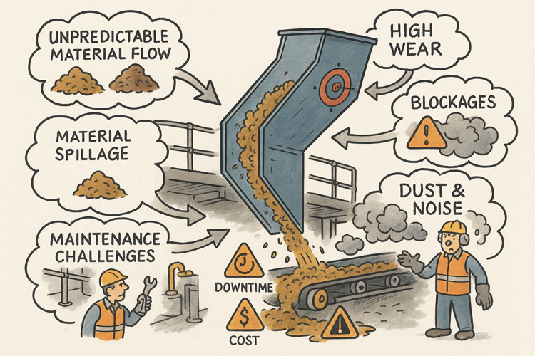
Many engineering challenges in metropolitan Melbourne are not greenfield projects. They involve existing buildings, operating facilities, constrained spaces, legacy assets, or staged upgrades that must integrate seamlessly with what is already in place. In these environments, relying on outdated drawings or manual measurements introduces risk โ€” misalignment, clashes, rework, and delays that can quickly erode budgets and schedules.

Hamilton By Design addresses this challenge by placing reality capture and engineering validation at the front end of projects. This ensures that every downstream decision is based on what truly exists on site, not what is assumed to exist.

For engineering teams working in and around South Yarra โ€” whether supporting manufacturing, infrastructure, plant upgrades, or specialist facilities โ€” this approach significantly reduces technical risk and increases confidence across all stakeholders.

LiDAR Scanning as a Foundation for Accuracy

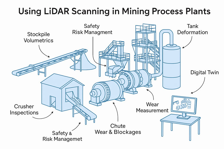
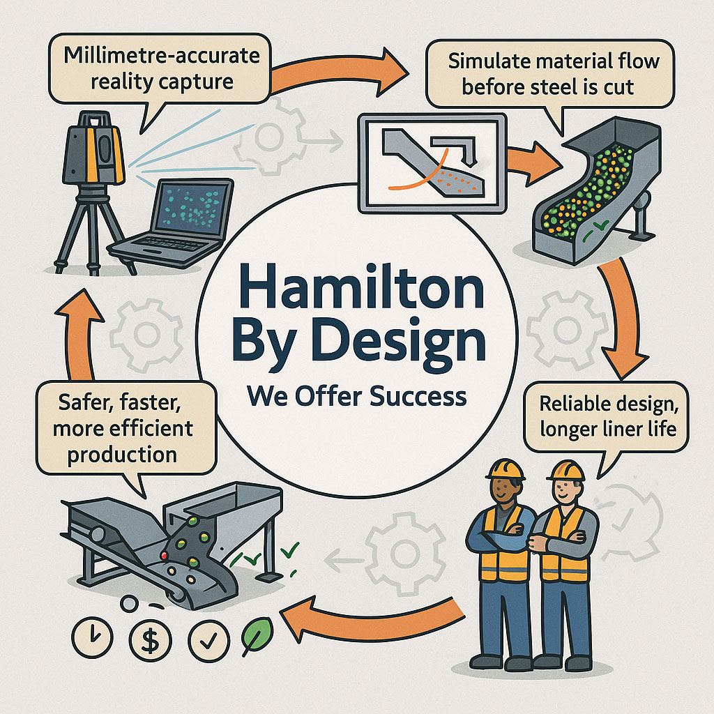
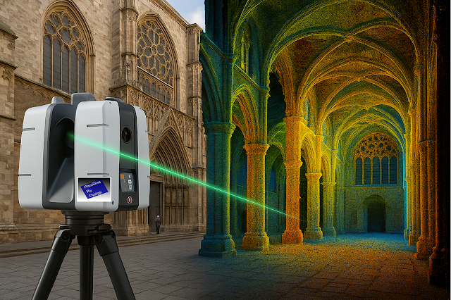
A key capability that differentiates Hamilton By Design is its use of engineering-grade LiDAR scanning. Unlike traditional surveys that capture selective points, LiDAR scanning records millions of measurements across an entire environment, producing a high-resolution digital representation of buildings, plant, structures, and surrounding context.

This data becomes a reliable reference point for engineers, designers, fabricators, and project managers alike.

LiDAR scanning enables:

  • Accurate capture of complex geometries and tight spaces
  • Clear identification of spatial constraints and interfaces
  • Early detection of clashes and access issues
  • Reduced need for repeat site visits
  • Improved coordination between disciplines

By converting physical assets into precise digital data, Hamilton By Design helps teams eliminate ambiguity and work from a single source of truth.

From Scan Data to Engineering Outcomes

Importantly, Hamilton By Design does not operate as a scanning-only service. The real value lies in how scan data is interpreted, validated, and converted into engineering outputs that directly support delivery.

Scan information is used to develop structured models, layouts, and documentation that reflect real-world conditions. This supports engineering activities such as:

  • Mechanical and structural modifications
  • Plant upgrades and equipment integration
  • Space planning and layout optimisation
  • Fabrication and installation planning
  • Asset documentation and as-built records

Because the work is led by experienced engineers, the focus is always on what needs to be built, installed, or modified, not just on creating visually impressive models.

Supporting Engineering Teams and Decision-Makers

In a business and engineering environment like South Yarra โ€” where projects are often time-sensitive and commercially driven โ€” external engineering support must be reliable, efficient, and technically sound.

Hamilton By Design integrates smoothly with internal teams, consultants, and contractors, providing additional technical depth without adding unnecessary complexity. The consultancy model is deliberately structured to support decision-makers who need clarity, not noise.

This means:

  • Clear communication of constraints and risks
  • Practical recommendations grounded in real site data
  • Deliverables aligned with fabrication and construction needs
  • Engineering documentation that supports approval and execution

The result is fewer surprises downstream and a smoother path from concept through to implementation.

Engineering for Brownfield and Live Environments

One of the most challenging aspects of modern engineering is working within live or brownfield environments โ€” facilities that cannot simply shut down for measurement, redesign, or rework. In these settings, accuracy and planning are critical.

Hamilton By Designโ€™s LiDAR-driven workflows are particularly well suited to these conditions. Rapid data capture minimises disruption on site, while the detailed digital record allows engineering work to continue remotely with confidence.

This approach supports safer planning, better coordination, and reduced exposure to operational risk โ€” outcomes that are highly valued by engineering leaders and project managers alike.

A Practical, Engineer-Led Philosophy

At its core, Hamilton By Design operates on a simple but powerful principle: engineering should be grounded in reality. By combining high-accuracy site data with deep engineering experience, the consultancy helps organisations make informed decisions, avoid costly mistakes, and deliver projects that work the first time.

For organisations operating in South Yarra and the broader Melbourne region, this means access to an engineering partner who understands both the technical and commercial pressures of modern project delivery.

Engineering Certainty in a Complex World

As engineering projects continue to increase in complexity, the margin for error continues to shrink. Those who invest early in accurate data and sound engineering judgement gain a clear advantage โ€” fewer delays, lower risk, and better outcomes.

Hamilton By Design provides that advantage by bridging the gap between the physical site and the engineering office. Through precise LiDAR scanning, practical engineering insight, and a strong focus on constructability, the consultancy supports confident, efficient, and reliable project delivery across Melbourneโ€™s most demanding environments.

LiDAR scanning Melbourne

Hamilton By Design logo displayed on a blue tilted rectangle with a grey gradient background

Our clients:

Name
Would you like us to arrange a phone consultation for you?
Address

From Reality to Results: How Hamilton By Design Delivers Engineering Success Through SolidWorks, Laser Scanning, and Intelligent Data Sharing

In complex engineering environments, success is rarely determined by a single calculation or drawing. It is determined by clarityโ€”clarity of information, clarity of intent, and clarity across every handover point between site, engineer, fabricator, and installer.

Hamilton By Design was created around this idea.

Across mining, heavy industry, infrastructure, and complex buildings, projects increasingly fail not because engineers lack capability, but because teams are working from incomplete, inconsistent, or unreliable information. Assumptions creep in. Measurements are approximated. Old drawings are trusted when they should not be. By the time fabrication or installation begins, risk has already been locked into the project.

Hamilton By Design approaches engineering differently. By combining engineer-led 3D laser scanning, SolidWorks-based mechanical design, and clear, practical data sharing, we reduce uncertainty at the very start of a projectโ€”and that single shift changes everything that follows.


Engineering begins with reality, not assumptions

Every project starts with an existing environment. Whether it is a CHPP in the Bowen Basin, a brownfield processing plant, a congested industrial building, or a live infrastructure asset, the reality on site is often more complex than any drawing suggests.

Hamilton By Design begins with capturing reality as it actually exists.

Using high-accuracy 3D laser scanning, site conditions are recorded in full context: structure, equipment, services, clearances, and access constraints. This is not about producing pretty visualsโ€”it is about creating a measurable, defensible digital reference that engineers can trust.

Unlike traditional measurement methods, laser scanning:

  • Captures millions of data points per second
  • Records geometry that is difficult or unsafe to measure manually
  • Preserves site information long after access windows close
  • Eliminates reliance on assumptions and partial measurements

For engineering teams, this changes the starting point of the project from โ€œwhat we think is thereโ€ to โ€œwhat we know is there.โ€


Why the FARO Focus S70 fits Hamilton By Designโ€™s workflow

4

Hamilton By Design uses the FARO Focus S70 laser scanner because it strikes the right balance between accuracy, portability, and ease of useโ€”qualities that matter in live industrial environments.

The Focus S70 is particularly well suited to:

  • Brownfield industrial sites
  • Mining and materials-handling plants
  • Buildings with tight access or active operations
  • Remote locations where speed and reliability matter

From a practical engineering perspective, its ease of deployment is critical. Scans can be completed quickly, often without disrupting operations, and without the need for complex setup or prolonged site occupation. This means:

  • Shorter site visits
  • Reduced exposure to operational risk
  • More flexibility around shutdown or access windows

Just as importantly, the data produced is clean, consistent, and immediately usable within downstream engineering workflows.

At Hamilton By Design, scanning is not outsourced or treated as a separate discipline. The same engineers who design the solution are involved in planning the scan, understanding what information matters, and verifying that the captured data is fit for purpose.

This engineer-led approach is one of the quiet but critical advantages that underpins project success.


Turning point clouds into engineering intelligence

Raw point clouds are powerfulโ€”but only if they are translated into meaningful engineering information.

This is where Hamilton By Designโ€™s use of SolidWorks becomes central to our workflow.

SolidWorks provides a flexible, parametric modelling environment that allows scanned data to be transformed into:

  • Accurate 3D mechanical models
  • Structural steel frameworks
  • Equipment layouts
  • Platforms, guards, chutes, and pipework
  • Assemblies designed specifically for fabrication and installation

By importing and referencing point clouds directly within SolidWorks, engineers are no longer designing in isolation. Every model is built in context, anchored to the real geometry of the site.

This approach delivers several key advantages:

  • Components fit the first time
  • Clearances are verified early
  • Interfaces with existing assets are fully understood
  • Installation sequencing can be considered during design

Rather than working around uncertainty, engineers are free to focus on optimisation, constructability, and safety.


SolidWorks as a collaboration platform, not just a design tool

One of the most underestimated strengths of SolidWorks is how well it supports collaboration and communication across project teams.

At Hamilton By Design, SolidWorks models are not treated as internal artefacts. They are shared, reviewed, and used as communication tools.

Through native files, neutral formats, and lightweight viewing options:

  • Fabricators can interrogate geometry before cutting steel
  • Site teams can visualise assemblies before installation
  • Clients can understand scope and interfaces without reading complex drawings
  • Engineers can identify risks long before they appear on site

This transparency dramatically reduces misinterpretation. When everyone is looking at the same modelโ€”derived from the same scanโ€”alignment improves naturally.

The result is fewer RFIs, fewer site surprises, and a smoother transition from design to construction.


Fabrication-ready outcomes, not theoretical models

Hamilton By Design places a strong emphasis on fabrication-ready deliverables.

Because models are developed with manufacturing in mind, downstream drawings are clearer, more consistent, and easier to build from. This includes:

  • Clear general arrangement drawings
  • Detailed part and assembly drawings
  • Logical BOMs aligned to procurement
  • Realistic tolerances based on site conditions

Fabricators appreciate drawings that reflect how things are actually builtโ€”not just how they look on screen. By grounding design in scan data and modelling within SolidWorks, Hamilton By Design produces outputs that align closely with workshop reality.

This reduces rework in the shop and stress during shutdowns, where time pressure is highest.


Technology alone does not deliver project success. The real differentiator is how information is shared.

Hamilton By Design places significant emphasis on making data:

  • Accessible
  • Understandable
  • Reusable

Point clouds, models, drawings, and supporting data are structured so they can be:

  • Revisited for future projects
  • Used by different stakeholders
  • Built upon rather than recreated

This is particularly valuable in long-life industrial assets, where todayโ€™s modification becomes tomorrowโ€™s interface.

By maintaining continuity of data across projects, clients build a digital assetโ€”not just a set of drawings. Over time, this reduces engineering cost, shortens project timelines, and increases confidence in future upgrades.


Ease of use drives adoption and value

One of the reasons the FARO Focus S70 and SolidWorks work so well together is their ease of use relative to the value they deliver.

Ease of use matters because:

  • It shortens learning curves
  • It reduces reliance on niche specialists
  • It allows engineers to stay focused on engineering, not software complexity

At Hamilton By Design, tools are selected not because they are fashionable, but because they support repeatable, reliable outcomes.

Scanning workflows are streamlined. Modelling practices are consistent. File structures are logical. This discipline ensures that projects scale smoothly, whether they involve a small retrofit or a major plant upgrade.


Reducing risk where it matters most

In industrial and mining projects, risk concentrates at interfaces:

  • New steel to old steel
  • New equipment to existing plant
  • Design intent to site execution

Hamilton By Designโ€™s integrated workflow reduces risk at these interfaces by ensuring:

  • Geometry is verified early
  • Interfaces are modelled, not guessed
  • Decisions are made with full context

This approach shifts risk out of the shutdown window and into the design phaseโ€”where it is cheaper and safer to manage.


A philosophy built around accountability

What truly differentiates Hamilton By Design is not just technology, but ownership.

The same team is responsible for:

  • Capturing site data
  • Interpreting it
  • Designing the solution
  • Producing fabrication-ready outputs

There is no fragmentation between disciplines, no handover gaps where responsibility becomes unclear. This single-source accountability builds trust with clients, fabricators, and site teams alike.


The compound effect of doing it right

When accurate data, SolidWorks-based design, and clear information sharing come together, the benefits compound:

  • Fewer site visits
  • Shorter design cycles
  • More confident fabrication
  • Smoother installations
  • Better long-term asset knowledge

Over time, this approach changes how projects are delivered. Engineering becomes proactive rather than reactive. Problems are solved digitally instead of on site. Teams collaborate instead of firefighting.


Engineering for real-world success

Hamilton By Designโ€™s workflow is not built around theory. It is built around what actually happens on site.

By grounding every project in reality through laser scanning, translating that reality into SolidWorks models, and sharing information clearly across all stakeholders, Hamilton By Design helps projects succeed where it matters most: in fabrication shops, during shutdowns, and on live sites.

In an industry where uncertainty is expensive and time is unforgiving, clarity becomes the most valuable engineering output of all.

That is the philosophy behind Hamilton By Designโ€”and the reason our approach continues to deliver consistent, practical success across complex engineering projects.

Hamilton By Design logo displayed on a blue tilted rectangle with a grey gradient background

Our Clients:

Name
Would you like us to arrange a phone consultation for you?
Address

Seeing the Unseen: How LiDAR Scanning is Transforming Mining Process Plants

In modern mining, where uptime is money and safety is non-negotiable, understanding the geometry of your process plant is critical. Every conveyor, chute, pipe rack, and piece of equipment must fit together seamlessly and operate reliably โ€” but plants are messy, dusty, and constantly changing. Manual measurement with a tape or total station is slow, risky, and often incomplete.

nfographic showing how LiDAR scanning is used in mining process plants, with illustrations of conveyors, crushers, tanks, mills and chutes. Labels highlight applications such as stockpile volumetrics, crusher inspections, safety and risk management, chute wear and blockages, mill wear measurement, tank deformation monitoring and creating digital twins.

This is where LiDAR scanning (Light Detection and Ranging) has become a game-changer. By capturing millions of precise 3D points per second, LiDAR gives engineers, maintenance planners, and operators an exact digital replica of the plant โ€” without climbing scaffolds or shutting down equipment. In this post, weโ€™ll explore how mining companies are using LiDAR scanning to solve real problems in processing plants, improve safety, and unlock operational efficiency.


What Is LiDAR Scanning?

LiDAR is a remote sensing technology that measures distance by firing pulses of laser light and recording the time it takes for them to return. Modern terrestrial and mobile LiDAR scanners can:

  • Capture hundreds of thousands to millions of points per second
  • Reach tens to hundreds of meters, depending on the instrument
  • Achieve millimeter-to-centimeter accuracy
  • Work in GPS-denied environments, such as inside mills, tunnels, or enclosed plants (using SLAM โ€” Simultaneous Localization and Mapping)

The output is a point cloud โ€” a dense 3D dataset representing surfaces, equipment, and structures with stunning accuracy. This point cloud can be used as-is for measurements or converted into CAD models and digital twins.


Why Process Plants Are Perfect for LiDAR

Unlike greenfield mine sites, processing plants are some of the most geometry-rich and access-constrained areas on site. They contain:

  • Complex networks of pipes, conveyors, tanks, and structural steel
  • Moving equipment such as crushers, mills, and feeders
  • Dusty, noisy, and hazardous environments with limited safe access

All these factors make traditional surveying difficult โ€” and sometimes dangerous. LiDAR enables โ€œno-touchโ€ measurement from safe vantage points, even during operation. Multiple scans can be stitched together to create a complete model without shutting down the plant.


Applications of LiDAR in Process Plants

1. Wear Measurement and Maintenance Planning

LiDAR has revolutionized how mines measure and predict wear on critical process equipment:

  • SAG and Ball Mill Liners โ€“ Portable laser scanners can capture the exact wear profile of liners. Comparing scans over time reveals wear rates, helping maintenance teams schedule relines with confidence and avoid premature failures.
  • Crusher Chambers โ€“ Scanning inside primary and secondary crushers is now faster and safer than manual inspections. The resulting 3D model allows engineers to assess liner life and optimize chamber profiles.
  • Chutes and Hoppers โ€“ Internal scans show where material buildup occurs, enabling targeted cleaning and redesign to prevent blockages.

Result: Reduced downtime, safer inspections, and better forecasting of maintenance budgets.


2. Retrofit and Expansion Projects

When modifying a plant โ€” installing a new pump, rerouting a pipe, or adding an entire circuit โ€” having an accurate โ€œas-builtโ€ model is crucial.

  • As-Built Capture โ€“ LiDAR provides an exact snapshot of the existing plant layout, eliminating guesswork.
  • Clash Detection โ€“ Designers can overlay new equipment models onto the point cloud to detect interferences before anything is fabricated.
  • Shutdown Optimization โ€“ With accurate geometry, crews know exactly what to cut, weld, and install โ€” reducing surprise field modifications and shortening shutdown durations.

3. Inventory and Material Flow Monitoring

LiDAR is not just for geometry โ€” itโ€™s also a powerful tool for tracking material:

  • Stockpile Volumetrics โ€“ Mounted scanners on stackers or at fixed points can monitor ore, concentrate, and product stockpiles in real time.
  • Conveyor Load Measurement โ€“ Stationary LiDAR above belts calculates volumetric flow, giving a direct measure of throughput without contact.
  • Blending Control โ€“ Accurate inventory data improves blending plans, ensuring consistent plant feed quality.

4. Safety and Risk Management

Perhaps the most valuable application of LiDAR is keeping people out of harmโ€™s way:

  • Hazardous Floor Areas โ€“ When flooring or gratings fail, robots or drones with LiDAR payloads can enter the area and collect data remotely.
  • Fall-of-Ground Risk โ€“ High walls, bin drawpoints, and ore passes can be scanned for unstable rock or buildup.
  • Escape Route Validation โ€“ Scans verify clearances for egress ladders, walkways, and platforms.

Every scan effectively becomes a permanent digital record โ€” a baseline for monitoring ongoing structural integrity.


5. Digital Twins and Advanced Analytics

A plant-wide LiDAR scan is the foundation of a digital twin โ€” a living, data-rich 3D model connected to operational data:

  • Combine scans with SCADA, IoT, and maintenance systems
  • Visualize live process variables in context (flow rates, temperatures, vibrations)
  • Run โ€œwhat-ifโ€ simulations for debottlenecking or energy optimization

As AI and simulation tools mature, the combination of geometric fidelity and operational data opens new possibilities for predictive maintenance and autonomous plant operations.


Emerging Opportunities

Looking forward, there are several promising areas for LiDAR in mining process plants:

  • Autonomous Scan Missions โ€“ Using quadruped robots (like Spot) or SLAM-enabled drones to perform routine scanning in high-risk zones.
  • Real-Time Change Detection โ€“ Continuous scanning of critical assets with alerts when deformation exceeds thresholds.
  • AI-Driven Point Cloud Analysis โ€“ Automatic object recognition (valves, flanges, motors) to speed up model creation and condition reporting.
  • Integrated Planning Dashboards โ€“ Combining LiDAR scans, work orders, and shutdown schedules in a single interactive 3D environment.

Best Practices for Implementing LiDAR

To maximize the value of LiDAR scanning, consider:

  1. Define the Objective โ€“ Are you measuring wear, planning a retrofit, or building a digital twin? This affects scanner choice and resolution.
  2. Plan Scan Positions โ€“ Minimize occlusions and shadow zones by preplanning vantage points.
  3. Use Proper Registration โ€“ Tie scans to a control network for consistent alignment between surveys.
  4. Mind the Environment โ€“ Dust, fog, and vibration can degrade data; choose scanners with appropriate filters or protective housings.
  5. Invest in Processing Tools โ€“ The raw point cloud is only the start โ€” software for meshing, modeling, and analysis is where value is extracted.
  6. Train Your Team โ€“ Build internal capability for scanning, processing, and interpreting the results to avoid vendor bottlenecks.

Infographic showing a 3D LiDAR scanner on a tripod surrounded by eight best-practice principles: start with clear objectives, plan your scanning campaign, prioritize safety, optimize data quality, ensure robust registration and georeferencing, establish repeatability, integrate with downstream systems, and train people with documented procedures

LiDAR scanning is no longer a niche technology โ€” it is rapidly becoming a standard tool for mining process plants that want to operate safely, efficiently, and with fewer surprises. From mill liners to stockpiles, from shutdown planning to digital twins, LiDAR provides a clear, measurable view of assets that was impossible a decade ago.

For operations teams under pressure to deliver more with less, the case is compelling: better data leads to better decisions. And in a high-stakes environment like mineral processing, better decisions translate directly to improved uptime, reduced costs, and safer workplaces.

The next time youโ€™re planning a shutdown, a retrofit, or even just trying to understand why a chute is plugging, consider pointing a LiDAR scanner at the problem. You may be surprised at how much more you can see โ€” and how much time and money you can save.

3D Scanning | Mining Surface Ops | 3D Modelling

Mechanical Engineering | Structural Engineering

Mechanical Drafting | Structural Drafting

3D CAD Modelling | 3D Scanning

Chute Design

SolidWorks Contractors in Australia

Hamilton By Design โ€“ Blog

Why 3D Point Clouds + Expert Modelers Are a Game-Changer for Your Projects

Infographic illustrating the 3D project data workflow, showing LiDAR scanners and drones capturing millions of data points, a designer modelling on a computer, and project teams validating accurate 3D data, highlighting benefits such as speed, accuracy, cost savings and project success.

Level Up your 3D Scans

In todayโ€™s world, accuracy and efficiency can make or break a project. Whether youโ€™re working in architecture, construction, engineering, or product design, you need reliable data โ€” and you need it fast. Thatโ€™s where 3D point clouds come in.

But thereโ€™s an important catch: not all scans are created equal. The difference between an average scan and a great one often comes down to the person behind the scanner. Having someone who understands 3D modeling take the scans can dramatically improve your projectโ€™s accuracy, reliability, and overall success.

Letโ€™s break down why.


The Power of 3D Point Clouds

Point clouds are essentially millions of tiny data points that capture the shape of an object, room, or entire site. Together, they create a highly detailed digital snapshot of the real world.

Hereโ€™s why this matters:

  • Precision you can trust โ€“ Point clouds deliver incredibly detailed measurements, capturing even the smallest curves and angles.
  • Nothing gets missed โ€“ Multiple scan angles ensure a full, 360ยฐ view of your site or object.
  • Speed and efficiency โ€“ What used to take hours (or days) with manual measurements can be captured in minutes.
  • Built-in context โ€“ Youโ€™re not just getting numbers; youโ€™re getting a complete digital environment to work inside.
  • Future-proof data โ€“ Once you have a scan, you have a permanent record of your space, ready to use months or years later.

From clash detection to as-built verification, point clouds save time, reduce errors, and make collaboration across teams smoother than ever.


Why the Person Taking the Scan Matters

While technology is powerful, experience is what makes the results reliable. Having a skilled 3D modeler operate the scanner can be the difference between a good project and a great one.

Hereโ€™s why an expert makes all the difference:

  • They know what matters โ€“ A modeler understands which details are critical for your project and ensures theyโ€™re captured.
  • Fewer gaps, fewer surprises โ€“ Experienced pros know how to plan scan positions to cover every angle and avoid blind spots.
  • Cleaner, more accurate data โ€“ They reduce common issues like noise, misalignment, or missing sections that can throw off your model.
  • Time saved, headaches avoided โ€“ No one wants to redo a scan halfway through a project. A professional ensures you get it right the first time.
  • Confidence from start to finish โ€“ When you know your model is accurate, you can move forward with design and construction decisions without second-guessing.

In short: a great scanner operator doesnโ€™t just deliver data โ€” they deliver peace of mind.


The Bottom Line

3D point clouds are already transforming how projects are planned and delivered. But pairing them with an experienced 3D modeler takes things to the next level.

Youโ€™ll get better data, faster turnarounds, and a far lower risk of costly mistakes. And when your goal is to deliver projects on time, on budget, and with zero surprises, thatโ€™s an edge you canโ€™t afford to miss.

Hamilton By Design logo displayed on a blue tilted rectangle with a grey gradient background

3D Modelling | 3D Scanning | Point Cloud Scanning

Chute Design in the Mining Industry

Infographic showing Hamilton By Designโ€™s engineering workflow, including millimetre-accurate LiDAR reality capture, material-flow simulation, optimised chute designs, and safer, more efficient production outcomes. Two workers in PPE highlight reliable design and longer liner life, with icons representing time, cost and quality benefits.

Getting Coal, Hard Rock, and ROM Material Flow Right

Chute design is one of the most critical yet challenging aspects of mining and mineral processing. Whether you are handling coal, hard rock ore, or raw ROM material, chutes and transfer stations are the unsung workhorses of every operation. When designed well, they guide material smoothly, minimise wear, and keep conveyors running. When designed poorly, they cause blockages, spillage, excessive dust, and expensive downtime.

Modern chute design has moved far beyond rules of thumb and back-of-the-envelope sketches. Today, successful projects rely on accurate as-built data, particle trajectory analysis, and advanced Discrete Element Method (DEM) simulation to predict, visualise, and optimise material flow before steel is cut. In this article, we explore why these tools have become essential, how they work together, and where software can โ€” and cannot โ€” replace engineering judgement.


Illustration showing common problems with poorly designed material-handling chutes. A chute discharges material onto a conveyor while issues are highlighted around it: unpredictable material flow, material spillage, maintenance challenges, high wear, blockages, and dust and noise. Warning icons for downtime and cost appear on the conveyor, and workers are shown dealing with the resulting hazards and maintenance tasks.

The Challenge of Chute Design

Coal and hard rock have very different flow behaviours. Coal tends to be softer, generate more dust, and be prone to degradation, while hard rock is more abrasive and can damage chutes if impact angles are not controlled. ROM material adds another level of complexity โ€” oversize lumps, fines, and moisture variation can cause hang-ups or uneven flow.

Chute design must balance several competing objectives:

  • Control the trajectory of incoming material to reduce impact and wear
  • Prevent blockages by maintaining flowability, even with wet or sticky ore
  • Manage dust and noise to meet environmental and workplace health requirements
  • Fit within existing plant space with minimal modification to conveyors and structures
  • Be maintainable โ€” liners must be accessible and replaceable without excessive downtime

Meeting all these goals without accurate data and simulation is like trying to design in the dark.


Illustrated graphic showing a tripod-mounted 3D laser scanner capturing millimetre-accurate as-built data in an industrial plant with conveyors and walkways. Speech bubbles highlight issues such as โ€œOutdated drawings donโ€™t tell the full storyโ€ and โ€œModifications rarely get documented.โ€ The scan data is shown being visualised on a laptop, with notes describing full coverage of conveyors, walkways, and services. Benefits listed along the bottom include faster data collection, fewer site revisits, safer shutdowns, accurate starting point for design simulation, and safer outcomes that ensure designs fit first time.

Capturing the Truth with 3D Scanning

The first step in any successful chute project is to understand the as-built environment. In many operations, drawings are outdated, modifications have been made over the years, and the real plant geometry may differ from what is on paper. Manual measurement is slow, risky, and often incomplete.

This is where 3D laser scanning changes the game. Using tripod-mounted or mobile LiDAR scanners, engineers can capture the entire transfer station, conveyors, surrounding steelwork, and services in a matter of hours. The result is a dense point cloud with millimetre accuracy that reflects the true state of the plant.

From here, the point cloud is cleaned and converted into a 3D model. This ensures the new chute design will not clash with existing structures, and that all clearances are known. It also allows maintenance teams to plan safe access for liner change-outs and other work, as the scanned model can be navigated virtually to check reach and access envelopes.


Understanding Particle Trajectory

Once the physical environment is known, the next challenge is to understand the particle trajectory โ€” the path that material takes as it leaves the head pulley or previous transfer point.

Trajectory depends on belt speed, material characteristics, and discharge angle. For coal, fine particles may spread wider than the coarse fraction, while for ROM ore, large lumps may follow a ballistic path that needs to be controlled to prevent impact damage.

Accurately modelling trajectory ensures that the material enters the chute in the right location and direction. This minimises impact forces, reducing wear on liners and avoiding the โ€œsplashโ€ that creates spillage and dust. It also prevents the material from hitting obstructions or dead zones that could lead to build-up and blockages.

Modern software can plot the trajectory curve for different loading conditions, providing a starting point for chute geometry. This is a critical step โ€” if the trajectory is wrong, the chute design will be fighting against the natural path of the material.


The Power of DEM Simulation

While trajectory gives a first approximation, real-world flow is far more complex. This is where Discrete Element Method (DEM) simulation comes into play. DEM models represent bulk material as thousands (or millions) of individual particles, each following the laws of motion and interacting with one another.

When a DEM simulation is run on a chute design:

  • You can visualise material flow in 3D, watching how particles accelerate, collide, and settle
  • Impact zones become clear, showing where liners will wear fastest
  • Areas of turbulence, dust generation, or segregation are identified
  • Build-up points and potential blockages are predicted

This allows engineers to experiment with chute geometry before fabrication. Angles can be changed, ledges removed, and flow-aiding features like hood and spoon profiles or rock-boxes optimised to achieve smooth, controlled flow.

For coal, DEM can help ensure material lands gently on the receiving belt, reducing degradation and dust. For hard rock, it can ensure that the energy of impact is directed onto replaceable wear liners rather than structural plate. For ROM ore, it can help prevent oversize lumps from wedging in critical locations.


Illustration of an optimised chute design showing material flow represented by green particles, with check marks and gear icons indicating improved efficiency and engineered performance.

๐Ÿ–ฅ Strengths and Limitations of Software

Modern DEM packages are powerful, but they are not magic. Software such as EDEM, Rocky DEM, or Altairโ€™s tools can simulate a wide range of materials and geometries, but they rely on good input data and skilled interpretation.

Key strengths include:

  • Ability to model complex, 3D geometries and particle interactions
  • High visualisation power for communicating designs to stakeholders
  • Capability to run multiple scenarios (different feed rates, moisture contents, ore types) quickly

However, there are limitations:

  • Material calibration is critical. If the particle shape, friction, and cohesion parameters are wrong, the results will not match reality.
  • Computational cost can be high โ€” detailed simulations of large chutes with millions of particles may take hours or days to run.
  • Engineering judgement is still needed. Software will not tell you the โ€œbestโ€ design โ€” it will only show how a proposed design behaves under given conditions.

Thatโ€™s why DEM is best used as part of a holistic workflow that includes field data, trajectory analysis, and experienced design review.


From Model to Real-World Results

When the simulation results are validated and optimised, the design can be finalised. The point cloud model ensures the chute will fit in the available space, and the DEM results give confidence that it will perform as intended.

This means fabrication can proceed with fewer changes and less risk. During shutdown, installation goes smoothly, because clashes have already been resolved in the digital model. Once commissioned, the chute delivers predictable flow, less spillage, and longer liner life.


Why It Matters More Than Ever

Todayโ€™s mining operations face tighter production schedules, stricter environmental compliance, and increasing cost pressures. Downtime is expensive, and the margin for error is shrinking.

By combining 3D scanning, trajectory modelling, and DEM simulation, operations can move from reactive problem-solving to proactive improvement. Instead of waiting for blockages or failures, they can design out the problems before they occur, saving both time and money.


Partnering for Success

At Hamilton by Design, we specialise in turning raw site data into actionable insights. Our team uses advanced 3D scanning to capture your transfer stations with precision, builds accurate point clouds and CAD models, and runs calibrated DEM simulations to ensure your new chute design performs from day one.

Whether youโ€™re working with coal, hard rock, or ROM ore, we help you deliver designs that fit first time, reduce maintenance headaches, and keep production running.

Contact us today to see how our integrated scanning and simulation workflow can make your next chute project safer, faster, and more reliable.

Mechanical Engineering | Structural Engineering

Mechanical Drafting | Structural Drafting

3D Laser Scanning | 3D CAD Modelling | 3D Scanning

Chute Design

SolidWorks Contractors in Australia

Hamilton By Design โ€“ Blog

Consulting Engineers

About Us โ€“ Hamilton By Design

Hamilton By Design | 3D Scanning | Sydney | Perth | Brisbane | Mount Isa | Lidar Scanning

Contact us

3D Scanning

How 3D Laser Scanning is Redefining Reality for Design, Construction & Heritage

Imagine standing before a centuries-old cathedral, where every carved arch, every stained-glass pane, every weathered stone holds centuries of stories. Capturing its true form and condition with tape measure and camera? Tedious and prone to errors. But with 3D laser scanning, you can digitally freeze every detailโ€”down to the imperfectionsโ€”turning reality into an exact, manipulable model.

In an age where precision, speed, and data-driven decisions are non-negotiable, 3D laser scanning is no longer โ€œnice to haveโ€โ€”itโ€™s essential. Letโ€™s explore what it is, why itโ€™s transformative, where itโ€™s being used most powerfully, and how you can harness its potential.

What Is 3D Laser Scanning?

At its core, 3D laser scanning sometimes called terrestrial laser scanning, (TLS) is the emission of laser pulses toward surfaces, recording the time it takes for those pulses to bounce back. From that comes a dense โ€œpoint cloudโ€ โ€” billions of precise data points mapping shape, texture, orientation, and distance.

These point clouds become high-fidelity models, maps, meshes, or BIM ready files. Whether youโ€™re scanning building exteriors, interiors, or industrial components, the result is more than just imageryโ€”itโ€™s measurable, analyzable geometry.

How It Works โ€” The Process

  1. Preparation & Planning

    Define what you need: the level of detail (LOD), resolution, range, and whether external conditions (light, weather) will interfere.

  2. Data Capture

    Position the scanner at multiple stations to cover all surfaces. Use targets or reference markers for alignment and capture with overlapping scans.

  3. Processing & Registration

    Merge scans to align them properly, clean noise, filter out irrelevant data (like people, moving objects), calibrate.

  4. Post-processing & Deliverables

    Convert point clouds into usable outputsโ€”floorplans, sections, elevations, 3D meshes, BIM models, virtual walkthroughs. Run analyses (clash detection, deformation etc.).

  5. Integration & Use

    Use the data in design, restoration, facility management, or documentation. The quality of integration (into BIM, GIS, CAD) is key to unlocking value.

ย 

Key Benefits

Benefit What It Means in Practice Real-World Impact
Extreme Precision Sub-millimetre to millimetre accuracy depending on the scanner and conditions. Less rework. Better fit for retrofit, renovation, or mechanical systems in tight tolerances.
Speed + Efficiency Collect large amounts of spatial data in far less time than traditional measurement. Faster project turnaround. Reduced site time costs.
Non-Contact / Low Disruption Good for fragile structures, hazardous or difficult-to-access places. Preserves integrity of heritage buildings; safer for workers.
Comprehensive Documentation Full visual & geometric context. Informs future maintenance. Acts as an archival record.
Better Decision Making & Conflict Detection Early clash detection; scenario simulation; what-if modelling. Avoids costly mistakes; helps build consensus among stakeholders.
Enhanced Visualisation & Communication Stakeholders can see exactly what exists vs. whatโ€™s being proposed. Improves client buy-in, regulatory approvals, fundraising.

ย 

Applications: Where It Shines

  • Architecture & Renovation: As-built models, restoration of heritage sites.

  • Infrastructure & Civil Engineering: Bridges, tunnels, rail track alignments.

  • Industrial & Manufacturing: Machine part audits, reverse-engineering, plant layout.

  • Heritage & Preservation: Documenting fragile monuments, archaeological sites.

  • Facility Management: Digital twins, maintenance, asset tracking.

  • Environment & Surveying: Terrain mapping, forestry, flood risk mapping (especially when combined with aerial systems or mobile scanning).

Challenges & Best Practices

Nothing is perfect. To get the most out of 3D laser scanning, anticipate and mitigate:

  • Environmental factors: Light, dust, rain, reflective surfaces can introduce noise.

  • Data overload: Massive point clouds are large; need strong hardware & efficient workflows.

  • Alignment & registration errors: Overlaps, control points, and calibration are vital.

  • Skill & Planning: Good operators + good planning = much better outcomes.

Key best practices:

  • Use reference targets for precise registration.

  • Capture overlap of 30-50% between scan positions.

  • Break project into manageable segments.

  • Clean noise early.

  • Think ahead about deliverables and how clients will use the data (design, BIM, VR etc.).

Case Studies & Stories

  • Heritage in Danger: A cathedral in Europe threatened by pollution and structural decay was laser scanned. The point cloud revealed minute deformations, enabling an accurate restoration planโ€”saving costs and preserving history.

  • Infrastructure Efficiency: A civil engineering firm reduced design clashes by 80% on a complex highway project by integrating scans with their BIM workflow.

  • Industrial Switch-Over: Manufacturing plant layout was reconfigured using scan data; downtime reduced because the virtual model matched reality better than the old blueprints.

Software, Tools & Ecosystem

While scanners are vital, the software ecosystem is what unlocks value. Tools that turn raw data into actionable insights include:

  • Reality capture tools (processing point clouds).

  • BIM / CAD integration (e.g. Revit, AutoCAD).

  • Visualization tools (VR, AR, walkthrough).

  • Data sharing & collaboration platforms.

  • Cloud storage / processing if large point clouds.

SaaS/cloud-based workflows are increasingly important to share among remote teams, facilitate stakeholder review, and ensure data is accessible beyond just technical users.

Why It Matters Now

  • Global pressures (heritage, sustainability, faster build cycles, remote work) are raising the bar.

  • Clients expect transparency, accuracy, minimized risk.

  • Regulatory compliance and โ€œas-builtโ€ requirements are stricter.

  • Digital twins & smart infrastructure demand high fidelity data.

3D laser scanning acts as a bridge: between physical world and digital twin; between heritage past and future; between design promise and build reality. Ifย you have a survey scan and want to make sense of point cloud data, contact Hamilton By Design

ย 
ย 
ย 
ย 

Our clients:

Name
Would you like us to arrange a phone consultation for you?
Address