The Real-World Accuracy of 3D LiDAR Scanning With FARO S150 & S350 Scanners

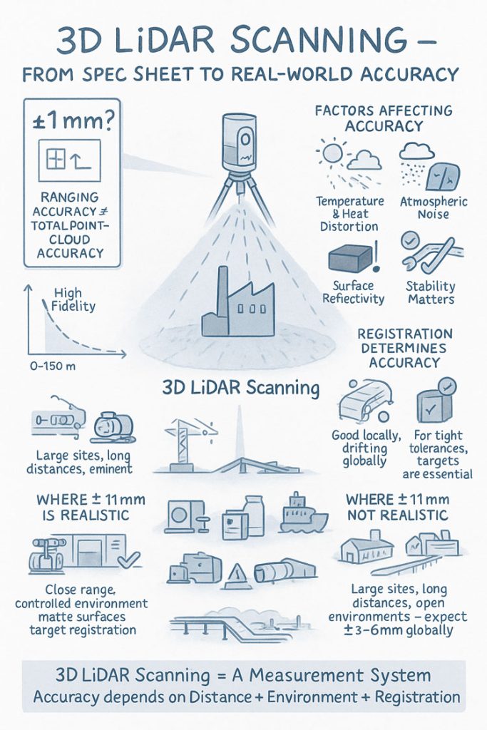
When people first explore 3D LiDAR scanning, one of the most eye-catching numbers in any product brochure is the advertised accuracy. FAROโ€™s Focus S150 and S350 scanners are often promoted as delivering โ€œยฑ1 mm accuracy,โ€ which sounds definitive and easy to rely on for engineering, mining and fabrication work. But anyone who has spent time working with 3D LiDAR scanning in real industrial environments understands that accuracy isnโ€™t a single number โ€” it is a system of interrelated factors.

This article explains what the ยฑ1 mm specification from FARO really means, how accuracy shifts with distance, and what engineers, project managers and clients need to do to achieve dependable results when applying 3D LiDAR scanning on live sites.


Infographic explaining 3D LiDAR scanning accuracy, showing a scanner capturing a building and highlighting factors that affect accuracy such as temperature, atmospheric noise, surface reflectivity and tripod stability. Includes diagrams comparing realistic versus unrealistic ยฑ1 mm accuracy, the impact of distance, environment and registration quality, and notes that large open sites typically achieve ยฑ3โ€“6 mm global accuracy.

1. What FAROโ€™s โ€œยฑ1 mm Accuracyโ€ Really Means in 3D LiDAR Scanning

The ยฑ1 mm number applies only to the internal distance measurement unit inside the scanner. It reflects how accurately the laser measures a single distance in controlled conditions.

It does not guarantee:

  • ยฑ1 mm for every point in a full plant model
  • ยฑ1 mm for every dimension extracted for engineering
  • ยฑ1 mm global accuracy across large multi-scan datasets

In 3D LiDAR scanning, ranging accuracy is just one ingredient. Real-world accuracy is shaped by distance, reflectivity, scan geometry and how multiple scans are registered together.


2. How Accuracy Changes With Distance in Real Projects

Even though the S150 and S350 list the same ranging accuracy, their 3D LiDAR scanning performance changes as distance increases. This is due to beam divergence, angular error, environment and surface reflectivity.

Typical real-world behaviour:

  • 0โ€“10 m: extremely precise, often sub-millimetre
  • 10โ€“25 m: excellent for engineering work, only slight noise increase
  • 25โ€“50 m: more noticeable noise and increasing angular error
  • 50โ€“100 m: atmospheric distortion and reduced overlap become evident
  • Near maximum range: still useful for mapping conveyors, yards and structures, but not suitable for tight fabrication tolerances

This distance-based behaviour is one of the most important truths to understand about 3D LiDAR scanning in field conditions.


3. Ranging Accuracy vs Positional Accuracy vs Global Accuracy

Anyone planning a project involving 3D LiDAR scanning must distinguish between:

Ranging Accuracy

The ยฑ1 mm value โ€” only the distance measurement.

3D Positional Accuracy

The true X/Y/Z location of a point relative to the scanner.

Global Point Cloud Accuracy

How accurate the entire dataset is after registration.

Global accuracy is the number engineers depend on, and it is normally around ยฑ3โ€“6 mm for large industrial sites โ€” completely normal for terrestrial 3D LiDAR scanning.


4. What Real Field Testing Reveals About FARO S-Series Accuracy

Independent practitioners across mining, infrastructure, CHPPs, plants and structural environments report similar results when validating 3D LiDAR scanning against survey control:

  • ยฑ2โ€“3 mm accuracy in compact plant rooms
  • ยฑ5โ€“10 mm across large facilities
  • Greater drift across long, open, feature-poor areas

These outcomes are not equipment faults โ€” they are the natural result of how 3D LiDAR scanning behaves in open, uncontrolled outdoor environments.


5. Why Registration Matters More Than the Scanner Model

Most real-world error in 3D LiDAR scanning comes from registration, not the laser itself.

Cloud-to-Cloud Registration

Good for dense areas, less reliable for long straight conveyors, open yards or tanks.

Target-Based Registration

Essential for high-precision engineering work.
Allows tie-in to survey control and dramatically improves global accuracy.

If your project needs ยฑ2โ€“3 mm globally, target control is mandatory in all 3D LiDAR scanning workflows.


6. Surface Reflectivity and Environmental Effects

Reflectivity dramatically affects measurement quality during 3D LiDAR scanning:

  • Matte steel and concrete return excellent data
  • Rusted surfaces return good data
  • Dark rubber, black plastics and wet surfaces reduce accuracy
  • Stainless steel and glass behave unpredictably

Environmental factors โ€” wind, heat shimmer, dust, rain โ€” also reduce accuracy. Early morning or late afternoon typically produce better 3D LiDAR scanning results on mining and industrial sites.


7. When ยฑ1 mm Is Actually Achievable

True ยฑ1 mm accuracy in 3D LiDAR scanning is realistic when:

  • Working within 10โ€“15 m
  • Surfaces are matte and reflective
  • Registration uses targets
  • Tripod stability is high
  • Conditions are controlled

This makes it suitable for:

  • Pump rooms
  • Valve skids
  • Structural baseplates
  • Reverse engineering
  • Small mechanical upgrades

But achieving ยฑ1 mm across a full plant, CHPP, or yard is outside the capability of any terrestrial 3D LiDAR scanning workflow.


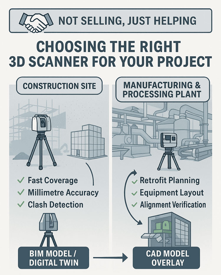
8. S150 vs S350: Which One for Your Accuracy Needs?

S150 โ€“ Engineering-Focused Precision

Ideal for industrial rooms, skids, structural steel and retrofit design work where short-to-mid-range accuracy is essential.

S350 โ€“ Large-Area Coverage

Perfect for conveyors, rail lines, yards, and outdoor infrastructure.
Global accuracy must be survey-controlled for tight tolerances.

Both scanners deliver excellent 3D LiDAR scanning performance, but the S150 is the engineering favourite while the S350 is the large-site specialist.


9. What to Specify in Contracts to Avoid Misunderstandings

Instead of stating:

โ€œScanner accuracy ยฑ1 mm.โ€

Specify:

  • Local accuracy requirement (e.g., ยฑ2 mm at 15 m)
  • Global accuracy requirement (e.g., ยฑ5 mm total dataset)
  • Registration method (mandatory target control)
  • Environmental constraints
  • Verification method (e.g., independent survey checks)

This ensures everyone understands what 3D LiDAR scanning will realistically deliver.


10. When a Terrestrial Scanner Is Not Enough

Do not rely solely on 3D LiDAR scanning for:

  • Machine alignment <1 mm
  • Bearing or gearbox placement
  • Certified dimensional inspection
  • Metrology-level tolerances

In these cases, supplement scanning with:

  • Laser trackers
  • Total stations
  • Metrology arms
  • Hybrid workflows

Conclusion: The Real Truth About 3D LiDAR Scanning Accuracy

FAROโ€™s S150 and S350 are outstanding tools for industrial 3D LiDAR scanning, but the ยฑ1 mm spec does not tell the full story. Real-world accuracy is a combination of:

  • Distance
  • Registration method
  • Surface reflectivity
  • Site conditions
  • Workflow discipline

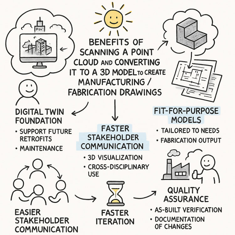
When used correctly, these scanners consistently deliver high-quality, engineering-grade point clouds suitable for clash detection, retrofit design, fabrication planning and as-built documentation.

3D LiDAR scanning is not just a laser โ€” it is an entire measurement system.
And when the system is applied with care, it produces reliable, repeatable data that reduces rework, improves safety, and strengthens decision-making across mining, construction, fabrication and industrial operations.

Where Is your project

3D Scanning Sydney CBD3D Scanning Brisbane CBD
3D Scanning across Melbourne3D Scanning across Perth
3D Scanning across Adelaide3D Scanning in The Hunter Valley
3D Scanning Mount Isa3D Scanning Emerald
3D Laser Scanning Central Coast3D Scanning in The Pilbara
3d Scanning other Areas of Australia3D Scanning Outside Australia
Hamilton By Design logo displayed on a blue tilted rectangle with a grey gradient background
Name
Address
You would like to:

3D CAD Modelling | 3D Scanning

3D Experience Platform Login

3D Scanning for Construction

Transforming Projects with 3D Scanning

3D LiDAR Scanning โ€“ Digital Quality Assurance

Digital Precision in Mining: How 3D Scanning Transforms Maintenance, Design, and Safety

Mining is no longer just about moving tonnes โ€” itโ€™s about precision, predictability, and performance.
Across Australiaโ€™s mining sector, the most forward-looking operators are adopting 3D scanning to transform the way they maintain and optimise chutes, hoppers, and material-handling systems.

At Hamilton By Design, weโ€™ve been applying advanced scanning technology to reduce downtime, improve plant design accuracy, and extend asset life.
You can read our detailed technical overview here:
๐Ÿ‘‰ 3D Scanning Chutes, Hoppers & Mining

But hereโ€™s the bigger picture โ€” why this shift matters for the future of mining.


From Manual Inspection to Measured Insight

Traditional inspections rely on tape measures, hand sketches, and assumptions.
3D laser scanning replaces that guesswork with millimetre-accurate data captured safely, often without shutting down production.

  • Reduced risk: Personnel spend less time inside confined spaces.
  • Shorter shutdowns: Entire structures can be captured in minutes.
  • Design-ready models: Engineers receive CAD-compatible data for modification or replacement.

This means decisions are made on facts, not estimates.


Integrating Data into the Design Cycle

The true value of scanning is unlocked when the data feeds directly into design and maintenance workflows.
Once a chute or hopper is scanned, engineers can:

  • Compare actual geometry to design intent.
  • Detect deformation, wear patterns, and misalignment early.
  • Pre-fit replacement liners or components in CAD โ€” reducing on-site rework.

This seamless link between field reality and digital design enables data-driven engineering, saving both time and capital.


A New Standard for Asset Reliability

3D scanning creates a living record of your assets.
Each scan becomes a baseline for future condition monitoring, allowing for proactive maintenance scheduling.

When combined with finite-element analysis (FEA) or wear modelling, site managers can predict failures before they happen.
That means safer plants, lower maintenance costs, and fewer unplanned stoppages.


Part of a Larger Digital Ecosystem

The rise of digital twins and predictive analytics in mining depends on accurate base geometry โ€” and thatโ€™s where scanning fits in.
By capturing exact dimensions, operators can:

  • Link asset data into their digital twin models.
  • Simulate flow behaviour and wear progression.
  • Train AI models using accurate 3D data.

3D scanning isnโ€™t just a tool โ€” itโ€™s the foundation of intelligent mining operations.


Why Hamilton By Design?

Our engineering approach combines field experience with digital precision.
We integrate scanning, modelling, and mechanical design into a single workflow โ€” from problem definition to implementable solutions.

Whether youโ€™re replacing a worn-out chute, upgrading a hopper, or building a new transfer station, our 3D scanning process gives you clarity, accuracy, and confidence.

Learn more about our methodology and recent projects here:
3D Scanning Chutes, Hoppers & Mining

Mechanical Engineering | Structural Engineering

Mechanical Drafting | Structural Drafting

3D CAD Modelling | 3D Scanning

Chute Design

SolidWorks Contractors in Australia

Hamilton By Design โ€“ Blog

Custom Designed – Shipping Containers

Coal Chute Design

Mechanical Engineers in Sydney

Choosing the Right 3D Scanner for Construction, Manufacturing, and Mining Projects

At Hamilton By Design, we know that 3D scanning has become an essential tool for modern engineering โ€” from capturing as-built conditions on construction sites to modeling complex processing plants and validating manufacturing layouts. But not all scanners are created equal, and selecting the right technology is crucial to getting reliable data and avoiding costly surprises later in the project.

3D Scanning for Construction Sites

For construction and infrastructure projects, coverage and speed are the top priorities. Terrestrial Laser Scanning (TLS) and LiDAR systems like the FARO Focus S70 are ideal for quickly capturing entire job sites with millimetre-level accuracy. These scanners allow engineers and project managers to:

  • Verify as-built conditions against design models
  • Detect clashes early in the process
  • Support accurate quantity take-offs and progress documentation

TLS works well in tough environments โ€” dust, sunlight, and complex geometry โ€” making it a perfect fit for active building sites.

3D Scanning for Manufacturing & Processing Plants

When it comes to manufacturing facilities and mining processing plants, accuracy and detail matter even more. Scans are often used for:

  • Retrofit planning and clash detection in tight plant rooms
  • Structural steel and conveyor alignment checks
  • Equipment layout for expansion projects

Here, combining TLS with feature-based CAD modeling allows us to deliver data that is usable for engineering design, ensuring that new equipment fits exactly as intended.

Infographic titled โ€˜Choosing the Right 3D Scanner for Your Projectโ€™ with the tagline โ€˜Not Selling, Just Helping.โ€™ The left side shows a construction site with a tripod-mounted 3D scanner and benefits listed: fast coverage, millimetre accuracy, and clash detection, leading to BIM model or digital twin outputs. The right side shows a manufacturing and processing plant with a scanner and benefits: retrofit planning, equipment layout, and alignment verification, leading to CAD model overlay results

Weโ€™re Here to Help

Hamilton By Design doesnโ€™t sell scanners โ€” we focus on providing unbiased, engineering-driven advice. If youโ€™re unsure which scanning approach is right for your project, weโ€™re happy to share our experience and guide you toward the best solution.

Feel free to get in touch to discuss your project needs โ€” whether itโ€™s a construction site, manufacturing facility, or processing plant, we can help you turn accurate scan data into actionable engineering insights.

3D Scanning for Construction Sites |  3D Scanning for Manufacturing | 3D Scanning for Processing Plants

Mechanical Engineering | Structural Engineering

Mechanical Drafting | Structural Drafting

3D CAD Modelling | 3D Scanning

Unlocking the Future of Design

Illustration of an engineering workspace where a tripod-mounted 3D LiDAR scanner captures a green point-cloud of an industrial pump assembly. Two engineers review scan data on a tablet beside technical drawings, while two others model components on computer workstations. A digital map of Australia is displayed in the background, highlighting Hamilton By Designโ€™s service locations including Perth, Brisbane, Sydney, and Melbourne. The scene emphasises advanced 3D scanning, digital engineering, and nationwide support.

3D Laser Scanning & Mechanical Engineering Solutions

In todayโ€™s fast-paced engineering and construction industries, precision and efficiency are everything. Whether youโ€™re managing a large-scale infrastructure project in Brisbane, creating a mechanical prototype in Perth, or needing accurate as-built data for a site in the Hunter Valley, 3D laser scanning and expert mechanical design services are game changers.

At Hamilton By Design, we specialise in connecting cutting-edge scanning technology with skilled mechanical designers and structural drafting services to deliver seamless, accurate solutions for every stage of your project.


The Power of 3D Laser Scanning

3D laser scanning is transforming the way engineers, architects, and manufacturers work. By capturing millions of data points with millimetre accuracy, laser scanning creates a highly detailed 3D representation of your asset, site, or structure.

Our team provides 3D laser scanning services in Perth, Brisbane, and Melbourne, as well as laser scanning in the Hunter Valley, helping clients save time and avoid costly rework. This technology is ideal for:

  • Capturing as-built conditions before design or construction.
  • Supporting plant upgrades and facility expansions.
  • Documenting heritage structures and complex geometries.
  • Reducing site visits with accurate digital models.

Reverse Engineering & Mechanical Design

In addition to scanning, we offer reverse engineering services in Perth and beyond. By combining point cloud data with CAD modelling, we can recreate components, optimise designs, and prepare manufacturing-ready files.

Our mechanical engineers and mechanical designers bring years of experience in 3D mechanical engineering, design and manufacturing mechanical engineering, and problem-solving for a wide range of industries. From bespoke machinery to process equipment, we deliver solutions that work.


Structural Drafting & Project Support

No project is complete without clear, accurate documentation. Our skilled drafters at Hamilton By Design provide high-quality structural drafting services that integrate seamlessly with your workflows.

Whether you need shop drawings, fabrication details, or BIM-ready models, our team ensures every line and dimension is correct โ€” saving you time and cost on-site.


Why Choose Hamilton By Design?

  • Nationwide Reach: Serving clients with 3D scanning services in Perth, Brisbane, and Melbourne, and supporting projects in the Hunter Valley.
  • Complete Solutions: From scanning to modelling to mechanical engineering design.
  • Accuracy & Efficiency: Reduce project risk and improve decision-making with reliable data.
  • Experienced Team: Skilled mechanical engineers and drafters who understand your industry.

Hamilton By Design logo displayed on a blue tilted rectangle with a grey gradient background

Ready to Get Started?

If youโ€™re looking for mechanical engineering companies that deliver precision, innovation, and reliability, Hamilton By Design is ready to help. Whether you need laser scanning in Perth or Brisbane, structural drafting, or full mechanical design services, our team can support your next project from concept to completion.

Contact us today to discuss your project requirements and find out how our 3D laser scanning and mechanical engineering design solutions can save you time and money.


Name
Would you like us to arrange a phone consultation for you?
Address

Next-Generation 3D Modelling & Scanning Advances in 2025

Illustrated infographic titled โ€œRecent Advancements in 3D Modelling and 3D Scanning.โ€ It features four themed sections around a central title. โ€œEnhanced Performanceโ€ shows a person working on a computer with faster response times for complex parts and assemblies. โ€œImproved Collaborationโ€ depicts two people discussing streamlined design communication. โ€œStreamlined Workflowsโ€ shows a microscope and gears representing improved management of part, assembly, and drawing processes. โ€œRicher Scan Dataโ€ shows a technician scanning an object and a computer displaying a dense point cloud model, emphasising greater accuracy and data density. The overall image highlights modern improvements in modelling, collaboration, workflows, and point cloud scanning.

1. Collaboration and Data Management

Collaboration is increasingly centred around 3D data. Modern platforms now let teams review, comment on, and markup native 3D models directly inside the design environment. Instead of relying solely on screenshots or static drawings, stakeholders can spin, section, and measure live models for better context. Real-time update notifications and cloud-connected revision control ensure that scanned 3D data and parametric CAD models stay synchronized โ€” critical when working with reality capture data that represents the as-built environment. Hybrid data management options combine local PDM systems with cloud platforms, supporting distributed teams handling massive point clouds or mesh data. This tight integration means that model changes โ€” whether from new design iterations or updated scans โ€” propagate instantly across the project team. Decision-making becomes more visual and informed, keeping everyone aligned around a single, authoritative 3D dataset. Collaboration is no longer a separate process but embedded into daily 3D workflows.


2. Smarter Part Modelling

3D modelling tools are now more intelligent and better suited for working with scan-derived geometry. Designers can quickly apply chamfers, fillets, and shells across complex surfaces, even those imported from meshes or point cloud extractions. Automated bend notch creation and sheet metal tools are optimized to work with geometry derived from scanning existing parts, making reverse-engineering and fabrication preparation much faster. Reference geometry patterning allows engineers to build parametric frameworks over point cloud regions, speeding up master model creation. Cleanup utilities now support selectively removing unnecessary features or smoothing noisy scan data without rebuilding the entire model history. These advances turn what used to be a labour-intensive process into a streamlined workflow that transforms raw reality capture data into production-ready models. The focus is on reducing friction between physical and digital โ€” allowing engineers to move quickly from scan to design, then to manufacturing.


3. Large Assembly Performance

Point cloud and mesh datasets are often extremely large, so performance improvements are critical. Modern CAD platforms now handle assemblies containing both traditional parametric models and massive scan data without bringing systems to a crawl. Engineers can duplicate components while maintaining mates, overlay scans onto assemblies to check fit, and perform interference detection even in lightweight modes. Visualization performance has been tuned for high-density point clouds, allowing smooth pan, zoom, and rotate interactions even with billions of points. Simplification and decimation tools let users strip out unneeded scan detail for faster load times while retaining critical geometry. Seamless transitions between lightweight review and full edit mode make it possible to work interactively with scanned environments. This capability is especially valuable for plant layout, construction validation, and retrofitting projects, where the ability to handle large, mixed-format 3D datasets directly within assemblies is a competitive advantage.


4. Enhanced Drawings and Documentation

Although 3D is the primary medium, 2D documentation remains essential โ€” especially for suppliers and manufacturing partners. Modern CAD environments generate drawings directly from parametric models or scan-based reconstructions, ensuring that documentation matches the latest as-built conditions. Multi-approval stamps, BOM quantity overrides, and standards compliance tools make it easy to document parts created from reverse engineering or field measurement data. Automatic view generation and model-based definition (MBD) help reduce the reliance on fully manual drawings, embedding dimensions and tolerances directly into the 3D model where possible. For projects using scans, section views can be cut through the point cloud or mesh to produce accurate reference drawings without redrawing geometry. These improvements ensure that documentation is both faster to produce and more accurate โ€” giving fabrication teams confidence that the deliverables reflect real-world conditions rather than idealized design intent.


5. Seamless ECAD/MCAD Integration

The convergence of 3D scanning and electronics integration is enabling more precise mechatronic design. Point cloud models of housings, enclosures, and factory floors can be combined with PCB outlines and component data for fit validation. Modern tools allow importing copper traces, vias, and keep-out regions into the mechanical model to run thermal or clearance checks directly against scanned geometry. This prevents collisions and ensures proper heat management early in the design cycle. Real-time synchronization between ECAD and MCAD domains means that if a scanned housing reveals unexpected tolerances, electrical designers can adjust their board layout accordingly. The result is a more accurate digital twin that accounts for both the designed and as-built states. This tighter integration avoids costly late-stage changes, shortens time-to-market, and ensures that mechanical and electrical systems are developed with a shared, reliable 3D reference that reflects physical reality.


6. Performance and Visualization

Visualization is where 3D scanning truly shines. GPU-accelerated engines now render massive point clouds, meshes, and parametric geometry in real time, allowing teams to virtually โ€œwalk throughโ€ captured environments or inspect reverse-engineered parts at full fidelity. Silhouette-based defeature tools can strip away irrelevant details while maintaining enough geometry for accurate reviews and clash detection. Cached mass property calculations extend to mesh and hybrid models, giving accurate weight and center of gravity data even from scan-derived parts. Photorealistic rendering using real-time ray tracing allows stakeholders to experience designs exactly as they will look, bridging the gap between scanned reality and proposed modifications. This level of visual fidelity improves collaboration, reduces the need for physical mock-ups, and accelerates stakeholder buy-in. High-quality 3D visualization is no longer a luxury โ€” it is a daily tool for engineers, designers, and decision-makers alike.


7. Future Outlook

The future of 3D modelling is increasingly driven by AI and reality capture. Expect CAD platforms to automatically recognize features within point clouds โ€” holes, slots, threads โ€” and generate parametric features with minimal user input. Cloud-native workflows will make it easier to process extremely large scan datasets without local performance bottlenecks. Automated drawing generation and model-based definition will continue to reduce documentation overhead, while digital twin technology will tie live sensor data to scanned geometry for ongoing validation. Generative design powered by AI will be able to work directly with scanned environments, proposing optimized solutions that account for real-world constraints. This convergence of scanning, modelling, and simulation promises a future where physical and digital coexist seamlessly โ€” enabling engineers to capture, design, simulate, and validate with unprecedented speed and accuracy, ultimately transforming how products, factories, and infrastructure are created and maintained.

Hamilton By Design logo displayed on a blue tilted rectangle with a grey gradient background

3D Modelling | 3D Scanning | Point Cloud Scanning

Our clients:

Name
Would you like us to arrange a phone consultation for you?
Address

3D Laser Scanning of Hotels

3D Scanning for Construction in Sydney

3d laser scanning for engineering

Itโ€™s Time to Level Up: Why Mechanical Engineering Consultants Are Key to Unlocking the Power of Point Cloud to 3D Modeling

In todayโ€™s competitive manufacturing and fabrication landscape, the difference between success and frustration often comes down to one thing: how well you capture and use data. Traditional methods of measurement, drafting, and design simply canโ€™t keep up with the complexity and pace of modern projects.

Enter point cloud scanning and 3D modeling โ€” a transformative approach that is reshaping how manufacturers, fabricators, and engineers work together. But as powerful as this technology is, getting the most from it takes more than just buying a scanner. It takes expertise, insight, and a partner who can integrate this digital transformation seamlessly into your workflows.

So, is it time to level up and engage mechanical engineering consultants who can make this happen?

We think so โ€” and hereโ€™s why.


From Point Cloud to 3D Model: A Game-Changer

When you scan a physical space, component, or assembly using modern laser scanning or photogrammetry, you capture millions of data points โ€” a digital twin of reality. Converting that data into a precise 3D model opens the door to benefits like:

  • Pinpoint Accuracy: Say goodbye to guesswork and human measurement errors.
  • Faster Iteration: Generate manufacturing and fabrication drawings quickly, test design variations digitally, and accelerate your project timelines.
  • Improved Collaboration: Give engineers, fabricators, and stakeholders a single source of truth that everyone can see and work from.
  • Risk Reduction: Spot interferences, clashes, and potential problems before they become costly rework in the shop or on-site.
  • Future-Proofing: Create a digital foundation for maintenance, upgrades, and retrofits years down the line.

This isnโ€™t just better engineering โ€” itโ€™s smarter business.


The Missing Piece: Expertise

Technology alone doesnโ€™t guarantee success. A high-resolution point cloud is just data โ€” and without the right people turning that data into insight, it wonโ€™t deliver its full value.

Thatโ€™s where mechanical engineering consultants come in. By partnering with experts who understand both the technology and the application, you gain:

  • Tailored Workflows: A consultant knows how to align the process with your unique needs, whether itโ€™s structural steel, piping systems, or custom machinery.
  • Best-Practice Modeling: Avoid bloated, unusable models or drawings that donโ€™t reflect fabrication realities.
  • Integrated Solutions: Consultants ensure your 3D models, fabrication drawings, and QA processes work seamlessly with your existing systems.
  • Strategic Insight: Move beyond simply โ€œdrawing whatโ€™s thereโ€ to rethinking processes, improving efficiency, and reducing total cost of ownership.

Why Now Is the Perfect Time

Market pressures are increasing. Labor costs are rising. Margins are under strain. Mistakes are expensive โ€” but digital solutions are more accessible than ever.

Your competitors are already exploring Industry 4.0 technologies like point cloud scanning, 3D modeling, and digital twins. The companies that succeed are the ones that move early, learn fast, and embed these practices into their operations.

Bringing in mechanical engineering consultants allows you to leapfrog the painful trial-and-error phase and start reaping the benefits from day one.


Level Up Your Engineering Today

If youโ€™re still relying on outdated measurement methods, 2D drawings, and siloed workflows, now is the time to level up. Scanning, modeling, and digital collaboration arenโ€™t โ€œnice-to-havesโ€ anymore โ€” theyโ€™re the foundation of modern manufacturing and fabrication.

Engage a trusted mechanical engineering consultant who can:

  • Capture your as-built environment accurately
  • Convert point clouds into actionable 3D models
  • Deliver fabrication-ready drawings
  • Help you reduce risk, save time, and improve quality

The future of engineering is here. Donโ€™t just keep up โ€” get ahead.

Consulting Engineers

3D Scanning | Mechanical Engineering | Hamilton By Design

Contact us