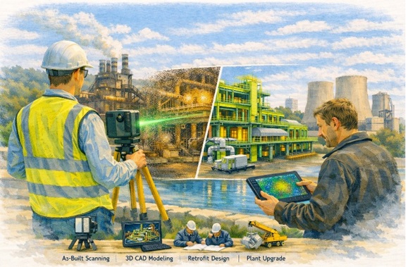
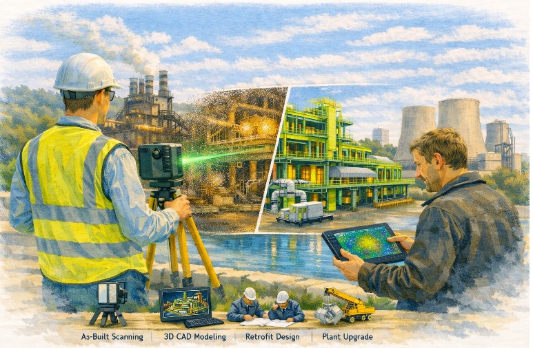
Engineering-grade 3D laser scanning, LiDAR and digital capture—delivered to site, anywhere in Australia.
When you’re working in a live facility, a remote site, or an aging asset that’s been modified a hundred times, the biggest risk is uncertainty. Missing dimensions. Out-of-date drawings. Unknown interferences. A “close enough” site measure that turns into rework, delays, and variations.
Hamilton By Design provides onsite scanning Australia wide to capture accurate, verifiable site conditions—so your engineers, designers, fabricators, and project managers can make confident decisions from day one.

Why onsite scanning matters
Onsite scanning is the fastest way to convert real-world assets into reliable digital information—especially in brownfield and retrofit environments where original documentation is incomplete or incorrect.
Our field capture provides a precise baseline for:
- As-built verification before upgrades, tie-ins, and shutdown works
- Retrofit engineering for legacy plants and facilities
- Clash detection and constructability checks before fabrication or installation
- Digital engineering workflows (scan-to-model / scan-to-drawings)
- Condition documentation for risk reduction, scope definition and handover records
In plain terms: the scan becomes the backbone of your project. If that backbone is broken (poor capture, gaps, or low confidence), everything downstream becomes harder—engineering, drafting, fabrication and installation.
Australia-wide coverage, site-ready delivery
We mobilise to projects across Australia—metro, regional and remote—bringing the scanning equipment, field workflow and practical site experience needed to operate safely and efficiently.
Typical deployment environments include:
- Mining & resources (processing plants, conveyors, workshops, pump stations)
- Industrial manufacturing (steel, smelting, production lines, utilities)
- Infrastructure and utilities (water, wastewater, power, transport assets)
- Commercial and government assets (plantrooms, services corridors, legacy buildings)
- Marine and ship repair (fit-up checks, reverse engineering, space claims)
If your site is difficult to access, operational, or time-restricted (e.g., night works), we can plan around your constraints.
What we scan onsite
We support a wide range of scanning objectives, including:
As-built capture for engineering and design
Capture existing steelwork, pipework, structures, platforms, equipment skids, services, and building geometry—so design is based on reality, not assumptions.
Retrofit and brownfield modification support
Ideal for upgrades where the facility has changed over time and legacy drawings don’t match current conditions.
Fabrication and installation verification
Use scans to confirm fitment, alignment, clearances, and integration points before committing to fabrication or mobilisation.
Reverse engineering and metrology-style capture
Where components are undocumented, worn, or custom—scanning provides a measurement foundation for remanufacture or replacement design.
Deliverables that suit real projects
Every project is different, so we align deliverables to what your team actually needs.
Common outputs include:
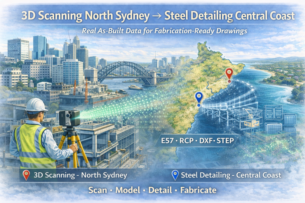
- Registered point clouds (for design coordination and record)
- 2D CAD outputs (elevations, sections, plans where required)
- 3D model-ready datasets to support engineering and drafting
- Digital verification notes to support design sign-off and QA
If you’re not sure what deliverable is best, we’ll recommend a practical option based on your scope, schedule, and how the data will be used downstream.
How our onsite scanning service works
- Scope & goals – what needs to be captured, why, and what level of detail is required
- Site requirements – access windows, inductions, permits, traffic management, WAH/EWP needs
- Onsite scanning mobilisation – safe, efficient field capture with a plan to minimise disruption
- Processing & registration – structured datasets prepared for engineering use
- Delivery & support – files issued with clear naming, coordination notes, and handover guidance
Safety and site integration
We operate with a strong focus on safe field work, practical site coordination, and minimal disruption to operations. Where required, we can work alongside site teams to manage access, exclusion zones, and staged capture.
Why Hamilton By Design
We’re an engineering-led team. That matters—because onsite scanning isn’t just “collecting data.” It’s collecting the right data, at the right density, in the right areas, with a clear understanding of how the information will be used for design, verification, and construction.
If you need confidence in your existing conditions—we can help.

Request onsite scanning Australia wide
If you have an upcoming retrofit, upgrade, verification, or design project and you need accurate site capture, get in touch.
Contact Hamilton By Design to discuss your site, your schedule, and the deliverables you need—anywhere in Australia.
Send us your site location, a brief scope, and any drawings/photos available, and we’ll advise the best scanning approach.