Why Graduate Engineers Quickly Become Addicted to LiDAR Scanning
Ask any graduate engineer what surprised them most in their first few years on the job and you’ll often hear the same answer:
“The drawings were wrong.”
Not maliciously wrong. Not incompetently wrong. Just… out of date, incomplete, or disconnected from what actually exists on site.
That realisation is often the moment graduate engineers discover LiDAR scanning — and once they do, it’s very hard to go back.
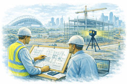
Across Greater Sydney, from dense inner-city refurbishments to industrial upgrades in the west, graduate engineers are finding that 3D laser scanning becomes indispensable almost as soon as they’ve worked with it properly. It’s not just helpful. It’s addictive — because it replaces uncertainty with clarity.
The graduate engineer’s first shock: reality doesn’t match the drawing
Most graduate engineers come out of university trained to think in:
- idealised geometry
- clean load paths
- well-defined dimensions
- drawings that represent truth
Then they step onto a live site in Sydney CBD, Surry Hills, Parramatta, Mascot, Alexandria, Chatswood, or North Sydney and realise something important:
Existing buildings, plant, and infrastructure are messy.
Services don’t run straight. Columns aren’t perfectly plumb. Steel has been modified, trimmed, plated, or shifted over decades. Mechanical equipment has been replaced multiple times, often without full documentation. In inner suburbs especially, space constraints mean “creative” solutions become permanent.
For a graduate engineer trying to do the right thing, this mismatch creates anxiety:
- Am I designing to the right information?
- What happens if this doesn’t fit?
- How confident should I be signing this off?
This is where LiDAR scanning changes everything.
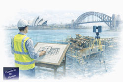
The first scan changes how graduates think
The first time a graduate engineer works with a real point cloud, something clicks.
Instead of guessing:
- they can measure directly
- they can see spatial relationships
- they can verify assumptions
- they can design in context
Suddenly, the question shifts from “what does the drawing say?” to “what actually exists?”
Once that shift happens, it’s very hard to go back to traditional workflows.
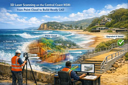
Hamilton By Design’s approach to engineering-led LiDAR scanning highlights this transition clearly — scanning isn’t just data capture, it’s digital quality assurance for engineering decisions.
👉 3D LiDAR Scanning & Digital Quality Assurance
https://www.hamiltonbydesign.com.au/home/3d-lidar-scanning-digital-quality-assurance/
For graduate engineers, this is often the first time they feel genuinely confident that their design inputs reflect reality.
Why LiDAR scanning becomes “addictive”
LiDAR scanning is addictive to graduate engineers for one simple reason:
It removes doubt.
Once you’ve experienced what it’s like to design from verified geometry, going back to hand measurements and assumptions feels risky — even irresponsible.
1. Confidence replaces guesswork
Instead of hoping clearances exist, graduates can prove they exist. Instead of estimating offsets, they can measure them. This builds technical confidence very quickly.
2. Mistakes become learning, not disasters
When designs are checked against a point cloud, errors are caught early — in the model, not on site. Graduates learn faster because mistakes are visible and correctable.
3. Engineering judgement develops faster
Seeing real-world geometry helps graduates understand:
- constructability
- installation constraints
- maintenance access
- tolerance accumulation
These lessons are difficult to teach from textbooks alone.
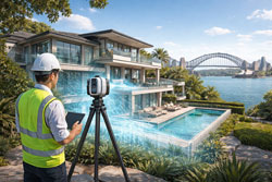
Inner Sydney makes scanning essential, not optional
In inner Sydney suburbs, LiDAR scanning is not a luxury — it’s often the only practical way to work.
Areas like:
- Sydney CBD
- Ultimo
- Pyrmont
- Surry Hills
- Redfern
- Alexandria
- Zetland
- Newtown
are characterised by:
- tight sites
- layered services
- heritage structures
- mixed-use refurbishments
- minimal tolerance for rework
Graduate engineers working on these projects quickly learn that:
- traditional site measurement is slow and disruptive
- access is limited and time-boxed
- errors are expensive and highly visible
Scanning allows:
- rapid capture without extended site shutdowns
- remote review and collaboration
- fewer repeat site visits
- better coordination between disciplines
Once graduates experience this efficiency, they naturally push for scanning on future projects.
How scanning supports better engineering decisions
LiDAR scanning doesn’t replace engineering judgement — it supports it.
Hamilton By Design frames scanning as a core part of engineering projects, not a bolt-on service. That distinction matters, especially for younger engineers still developing confidence.
👉 3D Laser Scanning for Engineering Projects
https://www.hamiltonbydesign.com.au/home/engineering-services/3d-laser-scanning/3d-laser-scanning-for-engineering-projects/
For graduate engineers, scanning supports:
Design verification
They can check whether:
- a beam is actually where the drawing says it is
- a pipe has enough fall
- a platform clears adjacent services
- access zones meet safety requirements
Better communication
Point clouds make design reviews clearer. Instead of explaining issues abstractly, graduates can show the problem in 3D context — especially helpful when working with senior engineers, fabricators, or clients.
Safer decisions
Designing from verified geometry reduces the risk of unsafe site improvisation. Graduates learn early that safety is tied directly to design certainty.
The “digital safety net” for early-career engineers
For many graduates, LiDAR scanning acts as a digital safety net.
Early in a career, the fear of “missing something obvious” is real. Scanning provides reassurance:
- Have I considered the surrounding structure?
- Did I allow enough clearance?
- Is this installable?
Instead of relying solely on experience they haven’t yet built, graduates can lean on measured reality.
Over time, this accelerates professional growth:
- better spatial awareness
- improved constructability thinking
- stronger questioning of legacy documentation
Ironically, the more graduates use scanning, the faster they develop the intuition to know when it’s needed — and when it’s not.
Greater Sydney: scanning as a standard workflow
Across Greater Sydney, LiDAR scanning is increasingly becoming standard practice for:
- building refurbishments
- industrial upgrades
- mechanical plant modifications
- structural alterations
- asset verification and compliance work
In western Sydney industrial areas, scanning supports large-scale plant and warehouse projects. In the north and east, it supports constrained commercial and infrastructure upgrades. In the inner suburbs, it often makes projects feasible at all.
Graduate engineers exposed to this environment quickly learn:
- projects that scan early run smoother
- fewer RFIs come back from site
- fabrication issues drop dramatically
- install teams trust the drawings more
Once they’ve seen this pattern a few times, scanning stops being a “special request” and becomes the default question:
“Can we scan this first?”
Why engineers struggle to go back once they’ve scanned
After working with LiDAR scanning, graduates often struggle with projects that don’t include it.
They notice:
- more uncertainty
- more site clarification calls
- more “we’ll fix it on site” language
- more reliance on assumptions
This is why scanning feels addictive — not because it’s flashy technology, but because it reduces friction at every stage of an engineering project.
For young engineers trying to build credibility, that reduction in friction is powerful. It allows them to:
- deliver cleaner designs
- ask better questions
- contribute meaningfully earlier in their careers
Digital quality assurance becomes a mindset
Perhaps the biggest shift LiDAR scanning creates is cultural.
Graduate engineers exposed to scanning early start to think in terms of digital quality assurance:
- verify before design
- check before fabrication
- confirm before installation
This mindset aligns closely with modern engineering governance, risk management, and professional accountability.
Hamilton By Design’s emphasis on scanning as digital quality assurance reflects this evolution — scanning isn’t about technology for its own sake, it’s about engineering confidence.
👉 https://www.hamiltonbydesign.com.au/home/3d-lidar-scanning-digital-quality-assurance/

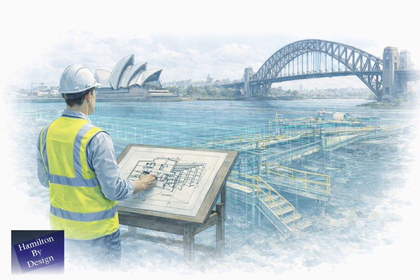
Final thoughts: once you see clearly, you don’t want to design blind again
For graduate engineers, LiDAR scanning often marks a turning point.
It’s the moment they realise engineering doesn’t have to rely on best guesses, inherited drawings, or incomplete information. It’s the moment they understand that good engineering starts with seeing clearly.
In Greater Sydney, especially across dense inner suburbs, that clarity isn’t optional — it’s essential.
Once graduate engineers experience what it’s like to design from reality, not assumption, LiDAR scanning stops being a tool and becomes part of how they think. And that’s why, once they’ve scanned properly, most engineers never want to design without it again.