AS 4324.1 Bulk Handling Equipment | Brownfield Stacker & Reclaimer Engineering
Mobile equipment for the continuous handling of bulk materials—such as stackers, reclaimers, and ship loaders—forms the backbone of Australia’s mining and export infrastructure. Many of these assets operate continuously in demanding environments, often well beyond their original design life.
Australian Standard AS 4324.1 provides essential guidance for the design and safe operation of this class of equipment. However, on many Australian mine sites, the practical application of the standard is misunderstood or only partially implemented, particularly when dealing with legacy machines and brownfield upgrades.
For asset owners and engineering managers, the challenge is rarely about greenfield compliance. It is about managing risk, extending asset life, and implementing upgrades without unplanned downtime.
Understanding AS 4324.1 in a Brownfield Context
AS 4324.1 addresses mobile equipment used for continuous bulk handling, including:
- Yard stackers and reclaimers
- Bucket wheel reclaimers
- Slewing and travelling machines
- Ship loaders at export terminals
While the standard establishes a strong baseline for design and safety, many operating machines:
- Pre-date the current revision of the standard
- Have undergone multiple undocumented modifications
- Operate under loading conditions that differ from original assumptions
In these situations, engineering judgement is required. Compliance becomes less about box-ticking and more about demonstrating that risks are understood, controlled, and managed over the asset lifecycle.
Common Challenges on Operating Mine Sites
Across coal handling plants, iron ore operations, and port facilities, several recurring issues emerge:
1. Incomplete or Outdated As-Built Information
Accurate geometry, slew limits, clearances, and structural interfaces are often unknown. This creates risk during upgrades and maintenance planning.
2. Fatigue and Structural Degradation
Large mobile machines experience cyclic loading across slewing, luffing, and travel motions. Fatigue cracking and unexpected failures require ongoing monitoring, not one-off assessments.
3. Access, Guarding, and Maintenance Compliance
Requirements evolve over time. Older machines may not meet current expectations for access systems, guarding, or safe maintenance practices.
4. Downtime Sensitivity
Stackers, reclaimers, and ship loaders are often production-critical assets. Upgrade windows are limited, and poor fit-up or rework can have significant commercial consequences.
Technology Supporting Modern Risk Management
While AS 4324.1 remains the foundation, modern technology allows asset owners to manage risk more effectively—particularly on brownfield equipment.
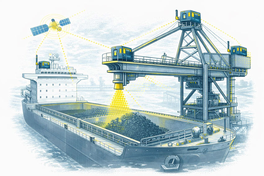
GPS Positioning and Controlled Operating Zones
Where GPS positioning is enabled, defined operating zones can be established to:
- Prevent interaction with stockpiles during rapid translation
- Automatically reduce slew or travel speed in high-risk zones
- Limit impact loads on critical components such as slew rings and fluffing gears
These systems are primarily productivity-driven, but they also reduce the likelihood of high-energy impacts that contribute to mechanical damage.
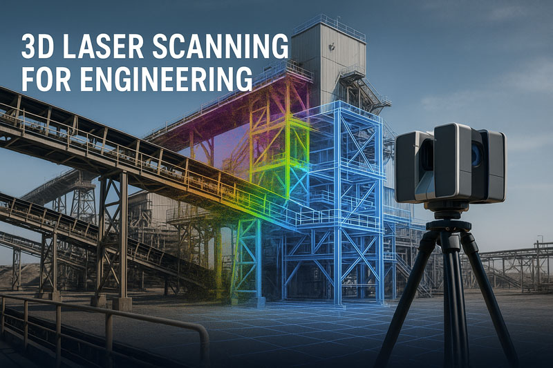
LiDAR Scanning as an Emerging Risk Layer
LiDAR scanning is not a replacement for traditional controls, and it is still evolving in this application. However, it can provide:
- Accurate spatial awareness of surrounding structures
- Verification of clearances and exclusion envelopes
- A secondary risk-management layer supporting operator decision-making
When combined with engineering-led interpretation, LiDAR contributes to a layered risk approach rather than acting as a standalone safety system.
Condition Monitoring and Real Load Understanding
Accelerometers installed across a range of frequencies can deliver valuable insight into:
- Actual operating loads
- Dynamic response during slewing, reclaiming, and travel
- Early indicators of fatigue-related issues
This data supports more informed maintenance decisions and provides evidence of how a machine is truly being used—often revealing load cases not considered in original designs.
Engineering-Led Compliance and Asset Life Extension
For brownfield assets, compliance with AS 4324.1 is best approached as a continuous engineering process, not a single milestone. This includes:
- Accurate reality capture and digital models
- Verification of clearances, interfaces, and structural geometry
- Informed upgrade design that fits the first time
- Risk-based decision-making supported by real operating data
This approach helps asset owners extend the life of critical machines while managing risk, performance, and availability.
How Hamilton By Design Supports Bulk Handling Assets
Hamilton By Design works with asset owners and engineering teams to support:
- Brownfield upgrades of stackers, reclaimers, and ship loaders
- Engineering-grade LiDAR scanning and as-built documentation
- Fit-for-purpose mechanical design for modifications and life-extension
- Independent engineering insight across OEM and site interfaces
Our focus is on engineering clarity, practical risk reduction, and minimising disruption to operations.
Talk to an Engineer About Your Asset
If you are planning a brownfield upgrade, life-extension, or risk review of mobile bulk-handling equipment, talk to an engineer at Hamilton By Design about how accurate data and practical engineering can support your next decision.
Our clients: