Why Low-Cost 3D Scanning Often Results in Higher Fabrication Costs

Engineering-grade LiDAR scan of an industrial plant showing point cloud and CAD overlay for fabrication accuracy

A Risk-Based Perspective for Project Managers and Company Directors

Executive Summary

The increasing availability of low-cost 3D scanning services has led to a perception that reality capture is a commoditised input to engineering projects. However, within fabrication-driven environmentsโ€”particularly in mining, heavy industry, and brownfield infrastructureโ€”this assumption is fundamentally flawed.

3D scanning is not an isolated deliverable; it is a foundational dataset upon which design, fabrication, and installation decisions are made. When this dataset lacks accuracy, completeness, or governance, downstream impacts emerge in the form of rework, delays, cost overruns, and elevated operational risk.

This paper outlines why low-cost scanning solutions frequently result in higher total project costs and provides a framework for evaluating scanning methodologies from a lifecycle and risk perspective.


1. The Role of Reality Capture in the Project Lifecycle

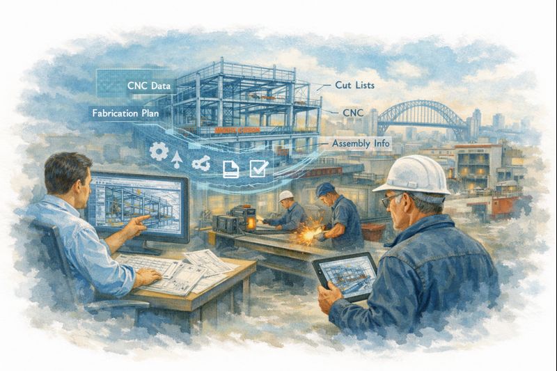
In modern engineering workflows, 3D scanning underpins a sequence of dependent activities:

  • Site capture (point cloud acquisition)
  • Data registration and validation
  • 3D modelling and design development
  • Detailing for fabrication
  • Installation and commissioning

Each stage inherits the quality of the preceding one. As a result, deficiencies in the initial scan propagate throughout the project lifecycle. Errors introduced at the data capture stage are rarely isolated and are often only fully realised during fabrication or installationโ€”when rectification costs are at their highest.


2. Accuracy as a Determinant of Fabrication Success

Fabrication processes require dimensional certainty. Tolerances associated with structural steel, piping systems, and mechanical assemblies are typically measured in millimetres. Deviations beyond these tolerances can render components unfit for purpose.

Lower-cost scanning methodologies, particularly those relying on unstructured workflows or drift-prone systems, often exhibit:

  • Accumulated positional error over distance
  • Inconsistent alignment between scan sets
  • Limited or absent survey control
  • Reduced reliability in complex industrial environments

While such datasets may appear visually acceptable, they frequently lack the dimensional integrity required for fabrication-grade outputs. The result is misalignment, rework, and increased reliance on site-based modification.


3. Cost Amplification Through Downstream Rework

The primary issue with low-cost scanning is not the initial saving, but the amplification of costs downstream.

A typical failure pathway includes:

  • Design based on inaccurate geometry
  • Fabrication to incorrect specifications
  • Installation conflicts and misalignment

At the installation stage, corrective actions may include:

  • Cutting and re-welding on site
  • Redesign under time constraints
  • Expedited fabrication of replacement components
  • Additional labour and supervision

A relatively small saving in scanning costs can therefore result in significant increases in total project cost, particularly in time-critical environments.


3D CAD Modelling Australia service banner for Hamilton By Design

4. Operational Risk and Downtime Implications

In industrial environments, downtime represents one of the most significant cost drivers. Inaccurate scan data introduces risks that extend beyond fabrication and into operations, including:

  • Extended shutdown durations
  • Delayed commissioning
  • Installation clashes
  • Disruption to production schedules

Given the high cost of downtime in mining and processing facilities, even minor delays can have substantial financial consequences. Low-cost scanning therefore introduces not only technical risk but also operational and commercial risk.


5. Visual Fidelity Versus Engineering Validity

A common misconception is that visually impressive scan data equates to engineering accuracy. Modern software platforms can present dense, colourised point clouds that appear complete and reliable.

However, visual quality does not guarantee:

  • Verified spatial accuracy
  • Consistent coordinate alignment
  • Defined tolerances
  • Reliable integration into engineering workflows

For decision-makers, the critical question is whether the data is demonstrably accurate and suitable for its intended engineering purposeโ€”not whether it appears visually convincing.


6. Data Completeness and Design Integrity

In addition to accuracy, completeness of data capture is essential.

Low-cost scanning approaches often result in incomplete datasets due to time constraints, access limitations, or insufficient planning. Common omissions include:

  • Undersides of structures
  • Connection points and bolt details
  • Congested or hard-to-reach areas
  • Critical interfaces between systems

Incomplete data forces engineers to make assumptions, which introduces uncertainty into the design process. This often leads to conservative design, increased material usage, additional site visits, and iterative revisions.


7. Governance and Traceability

Effective project delivery requires a clear and controlled data environment.

Engineering-grade scanning workflows typically include:

  • Registration reports and validation metrics
  • Defined coordinate systems
  • Version control and data management
  • Traceability from scan to model to drawing

Low-cost scanning services often lack these controls, resulting in:

  • Multiple conflicting datasets
  • Poor coordination between disciplines
  • Limited accountability
  • Increased risk during audits or dispute resolution

Without a single source of truth, project risk increases significantly.


8. Fabrication Constraints and Irreversibility

Fabrication environments operate on precision and adherence to documented design. Workshops do not reinterpret dataโ€”they execute it.

When inaccurate scan data informs fabrication:

  • Errors are embedded in physical components
  • Materials and labour are consumed unnecessarily
  • Corrections become costly and complex

By the time issues are identified, the opportunity for low-cost correction has passed.


9. Reframing the Investment Decision

The evaluation of scanning services should be based on total project cost rather than initial expenditure.

  • Low-cost scanning: lower upfront cost, higher downstream risk
  • Engineering-grade scanning: moderate upfront cost, reduced risk and greater predictability

Given that scanning represents a small proportion of overall project cost, decisions based solely on price are often misaligned with project objectives.


10. A Structured Approach to Risk Mitigation

To reduce risk and improve outcomes, the following approach is recommended:

  • Define accuracy requirements aligned with fabrication tolerances
  • Select appropriate scanning methodologies
  • Implement controlled data acquisition and registration
  • Validate datasets prior to design development
  • Integrate scan data into coordinated modelling workflows
  • Maintain governance and version control throughout the project lifecycle

This ensures that reality capture supports, rather than undermines, project delivery.


Conclusion

Low-cost 3D scanning services may appear cost-effective at the outset, but they frequently result in increased costs, delays, and risk when evaluated across the full project lifecycle.

For project managers and company directors, the critical consideration is the integrity of the data informing engineering decisions. In fabrication-driven environments, accuracy and reliability are essential.

Investment in engineering-grade scanning should therefore be viewed not as an optional expense, but as a risk mitigation strategy that underpins successful project delivery.


Related Services

To support fabrication certainty and reduce project risk, the following engineering-led services are available:

These services are specifically structured to deliver accurate, validated datasets suitable for engineering design and fabrication.


Ensuring Confidence in Fabrication Data

Where projects involve brownfield modifications, shutdown execution, or critical structural and mechanical installations, the reliability of underlying data is a key determinant of success.

Engineering-grade 3D LiDAR scanning provides a controlled and verifiable foundation for design, reducing uncertainty and enabling informed decision-making throughout the project lifecycle.

At Hamilton By Design, the focus is on delivering fit-for-purpose engineering dataโ€”ensuring that models, drawings, and fabrication outputs align with real-world conditions.


3D LiDAR scanning and 3D modelling service button โ€” laser scanner capturing a point cloud for engineering and CAD modelling
Mechanical engineering services

Independent Review of Existing Scan Data

Where scan data has already been captured, an independent review can be undertaken to assess its suitability for engineering and fabrication use.

This includes evaluation of:

  • Registration quality and alignment integrity
  • Dimensional accuracy relative to project requirements
  • Completeness of captured geometry
  • Suitability for downstream modelling and detailing

This approach provides clarity before further design or fabrication investment is committed.


Hamilton By Design logo displayed on a blue tilted rectangle with a grey gradient background

Contact Us – Talk to Us

For further discussion regarding project requirements or to review an existing scanning approach:

Hamilton By Design
Email: info@hamiltonbydesign.com.au
Website: www.hamiltonbydesign.com.au

Enquiries are welcome to arrange a brief discussion to determine the most appropriate approach for achieving reliable, fabrication-ready outcomes.

Name
Would you like us to arrange a phone consultation for you?
Address

Our clients

Fabrication Integrated Modelling (FIM):

Sydney manufacturing workshop using Fabrication Integrated Modelling to connect engineering design, CNC data, and local steel fabrication.

Fabrication Integrated Modelling (FIM): Why Itโ€™s the Future for Local Fabricators

Why It Is the Future for Local Fabricators

The fabrication industry is undergoing a fundamental transformation. Increasing project complexity, tighter tolerances, compressed schedules, labour shortages, and rising material costs are placing unprecedented pressure on fabricators โ€” particularly local workshops operating in competitive markets. At the same time, clients are demanding greater certainty: certainty of fit, certainty of schedule, and certainty of cost.

Traditional fabrication workflows, built around 2D drawings and manual interpretation, are no longer sufficient to meet these expectations. They rely heavily on experience, assumptions, and rework โ€” all of which introduce risk. In this environment, Fabrication Integrated Modelling (FIM) is emerging not as a luxury, but as a necessity.

FIM represents a shift from drawing-based fabrication to model-driven fabrication, where a single, coordinated digital model governs design intent, fabrication detailing, procurement, machining, assembly, and installation. For local fabricators, this shift offers a path to higher productivity, improved margins, and long-term relevance in an evolving industry.


What Is Fabrication Integrated Modelling (FIM)?

Fabrication Integrated Modelling is a methodology where the fabrication model becomes the primary source of truth across the entire project lifecycle. Instead of treating design, drafting, fabrication, and installation as disconnected stages, FIM integrates them into a continuous digital workflow.

In an FIM environment:

  • Engineering intent is embedded directly into the model
  • Fabrication constraints are considered from the outset
  • Quantities, tolerances, and interfaces are defined digitally
  • Fabrication data flows directly to machines and shop documentation
  • Installation sequencing is validated before material is cut

The model is not merely a visual aid โ€” it is a fully informed digital prototype of the fabricated asset.

From Drawings to Data: A Fundamental Shift

Historically, fabrication has relied on 2D drawings as the primary communication tool. These drawings require interpretation by drafters, trades, and supervisors, each introducing assumptions based on experience and context. While this approach has worked for decades, it becomes increasingly fragile as projects grow more complex.

Fabrication Integrated Modelling replaces interpretation with explicit data. Hole locations, weld preparations, connection details, clearances, and tolerances are all defined within the model. This reduces ambiguity and ensures that everyone โ€” from estimator to machine operator โ€” is working from the same information.

The result is a dramatic reduction in errors, clarifications, and rework.


Why FIM Is Gaining Momentum Now

Several industry pressures are accelerating the adoption of FIM:

  • Increasing complexity of industrial and infrastructure projects
  • Reduced tolerance for errors during shutdowns and brownfield upgrades
  • Labour shortages and loss of experienced trades
  • Higher expectations for schedule and cost certainty
  • Growing integration of CNC and automated fabrication equipment

FIM addresses these challenges by improving coordination, predictability, and efficiency at the source โ€” before fabrication begins.


Fabrication Integrated Modelling in a Sydney workshop showing engineers and fabricators using a shared 3D model to drive CNC fabrication and steel assembly.

Key Benefits of Fabrication Integrated Modelling

Reduced Errors and Rework

Rework is one of the most significant drains on fabrication profitability. Errors discovered on the workshop floor or during installation often result in cascading impacts: delays, additional labour, material waste, and strained relationships with clients.

By resolving interfaces, clashes, and tolerances digitally, FIM enables fabricators to identify and eliminate issues before steel is cut. Assemblies are tested virtually, connections are validated, and fit-up risks are significantly reduced.

This proactive approach shifts problem-solving upstream, where changes are faster, cheaper, and less disruptive.


Improved Fabrication Efficiency and Throughput

Fabrication speed is not achieved by rushing work โ€” it is achieved by removing uncertainty. FIM provides clarity on what needs to be fabricated, in what order, and to what tolerance.

Benefits include:

  • Clear fabrication sequencing
  • Reduced downtime waiting for clarifications
  • Better planning of labour and machine utilisation
  • More predictable workshop flow

Local fabricators using FIM often report smoother operations, fewer interruptions, and a higher percentage of โ€œright-first-timeโ€ components.


Better Use of Skilled Labour

Skilled trades are becoming harder to find and retain. Fabrication Integrated Modelling helps maximise the value of skilled workers by giving them better information, not more guesswork.

Fitters receive assemblies that align as expected. Welders focus on quality rather than correcting geometry. Supervisors make decisions based on accurate model data rather than assumptions. Apprentices gain clarity and confidence by working from model-based instructions.

Rather than replacing experience, FIM captures and amplifies it.


Seamless Integration with CNC and Fabrication Equipment

One of the strongest advantages of FIM is its ability to connect directly with modern fabrication equipment. The same model used for coordination and verification can generate machine-ready data, including:

  • NC files for beam lines and plate processors
  • Cut lists and nesting data
  • Part numbers and assembly marks
  • Machining references

This eliminates duplication of effort and reduces the risk of transcription errors. It also shortens the time between design approval and fabrication start, improving responsiveness to project changes.


Competitive Advantage for Local Fabricators

Local fabricators often compete with offshore suppliers on price alone โ€” a contest that is difficult to win. FIM allows local workshops to compete on value rather than cost.

Key differentiators enabled by FIM include:

  • Faster response to changes
  • Higher confidence in fit-up for complex or brownfield sites
  • Reduced installation risk
  • Stronger collaboration with engineers and constructors

When site conditions change โ€” as they inevitably do โ€” local fabricators using FIM can adapt quickly, update models, and deliver revised components without significant disruption. This agility is a powerful advantage over remote fabrication alternatives.


FIM in Brownfield and Upgrade Projects

Brownfield projects present some of the greatest challenges in fabrication. Existing assets rarely match legacy drawings, and tolerances are often tight. Discovering misalignment during installation can result in costly delays and extended shutdowns.

Fabrication Integrated Modelling, often combined with accurate site capture, allows fabricators to design and fabricate components that align with actual site conditions rather than assumptions.

This approach reduces:

  • On-site modifications
  • Temporary works
  • Installation delays
  • Safety risks associated with forced fit-ups

For local fabricators servicing industrial plants and operational facilities, FIM is rapidly becoming an expected capability.


Financial Benefits: Protecting Margins, Not Just Schedules

While FIM is often associated with speed and accuracy, its most important benefit may be margin protection.

Model-based workflows enable:

  • More accurate pricing through reliable quantities
  • Reduced contingency allowances
  • Predictable labour and machine hours
  • Lower material waste
  • Fewer disputes and variations

By increasing certainty, FIM allows fabricators to price work confidently rather than defensively. Over time, this leads to healthier margins and more sustainable operations.


Earlier Engagement and Better Project Outcomes

Fabricators who adopt FIM often find themselves involved earlier in projects. Engineers and asset owners increasingly recognise the value of fabrication input during design development.

Early collaboration enables:

  • Design for manufacture and assembly
  • Smarter connection strategies
  • Reduced installation complexity
  • Improved safety outcomes

This shifts the fabricatorโ€™s role from reactive supplier to active project partner, strengthening relationships and improving project outcomes for all parties.


Overcoming Barriers to Adoption

Adopting Fabrication Integrated Modelling requires investment โ€” not only in software and systems, but in people and processes. Common challenges include:

  • Training requirements
  • Changes to established workflows
  • Initial productivity adjustments
  • Cultural resistance to new methods

Successful fabricators address these challenges incrementally. They start with pilot projects, focus on repeatable wins, and work closely with engineering and modelling partners to build capability over time.

The risk of maintaining outdated workflows is increasingly greater than the risk of change.


The Future of Fabrication: Integrated Digital Ecosystems

FIM is not the final destination โ€” it is the foundation for a more connected fabrication industry. As digital maturity increases, fabrication models will increasingly link to:

  • Digital twins
  • Quality assurance records
  • Traceability and compliance systems
  • Asset management platforms
  • Automated inspection and verification

In this future, the fabrication model becomes a long-term asset, supporting not only construction but operation and maintenance.


Why Fabrication Integrated Modelling Is the Future for Local Fabricators

Local fabrication is not disappearing โ€” it is evolving. Workshops that continue to rely solely on 2D drawings and manual processes will face increasing pressure from cost, risk, and competition. Those that embrace Fabrication Integrated Modelling will position themselves for long-term success.

By adopting FIM, local fabricators can:

  • Deliver higher quality with greater confidence
  • Reduce rework and wasted effort
  • Protect margins in competitive markets
  • Strengthen relationships with engineers and clients
  • Build resilient, future-ready businesses

Fabrication Integrated Modelling is not about replacing trades or experience. It is about supporting them with better information, clearer intent, and integrated workflows.

For local fabricators willing to invest in capability and collaboration, FIM is not just the future โ€” it is the pathway to remaining relevant, competitive, and profitable in an increasingly digital industry.

3D LiDAR scanning and 3D modelling service button โ€” laser scanner capturing a point cloud for engineering and CAD modelling
Mechanical engineering services
Name
Would you like us to arrange a phone consultation for you?
Address
3D CAD Modelling Australia service banner for Hamilton By Design

3D CAD Modelling Australia service banner for Hamilton By Design


CHPP Engineering title graphic featuring bold white text reading "CHPP Engineering" centred on a blue rounded rectangle background.
Pipework Drafting title graphic featuring bold white text reading "Pipework Drafting" centred on a blue rounded rectangle background.
3D LiDAR Scanning for Engineering Projects title graphic featuring bold white text on a blue rounded rectangle background.


Finite Element Analysis (FEA) engineering simulation button
Structural drafting services button
Mechanical drafting services button


Australian Drafting logo featuring bold white text reading "Australian Drafting" centred on a blue rounded rectangle background.
Engineering Governance title graphic featuring bold white text reading "Engineering Governance" centred on a blue rounded rectangle background.
Engineering-Grade LiDAR Scanning title graphic featuring bold white text on a blue rounded rectangle background.


Mechanical drafting services button
Structural drafting services button


Fabrication and product design services
3D CAD Modelling Australia service banner for Hamilton By Design
Mechanical, Structural & Pipework Drafting service banner by Hamilton By Design featuring white text on a blue background.


3D LiDAR scanning and 3D modelling service button โ€” laser scanner capturing a point cloud for engineering and CAD modelling
Mechanical engineering services