Every Shutdown Matters โ€“ Engineering-Led Scanning with FARO LiDAR for As-Builts

Illustration showing LiDAR scanning workflow for industrial shutdown from capture to installation.

Every Shutdown Matters โ€“ FARO LiDAR for As-Built Scanning

In heavy industry, a shutdown is not just another project milestone โ€” it is the most expensive window on the calendar. Production stops, contractors mobilise, and every hour has a dollar value attached. When something does not fit, the cost is immediate and visible. This is why every shutdown matters, and why the approach to measurement and design before the outage has become critical.

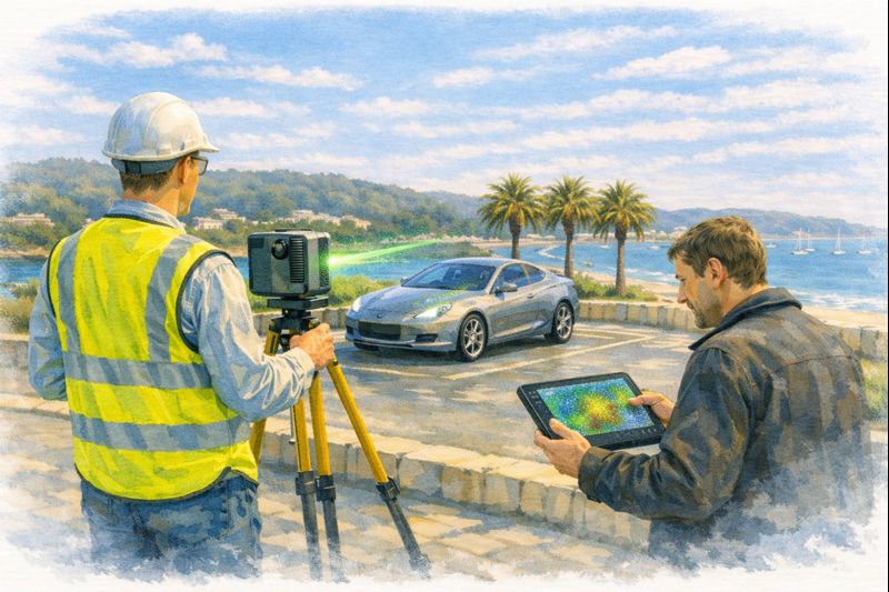
Traditional site measurement relies on tape measures, sketches, and assumptions about existing conditions. In brownfield environments those assumptions are often wrong. Steel moves, plant is modified without drawings, and tolerances stack up over decades. Engineering-led 3D scanning, particularly using FARO terrestrial LiDAR for as-built capture, has changed the way shutdowns are planned and delivered.


Engineering-led LiDAR scanning sequence from downtime to online restart.

From Guesswork to Measured Reality

A terrestrial LiDAR scanner captures millions of accurate points across an entire facility. Instead of a handful of manual dimensions, designers receive a complete digital replica of the plant โ€” every beam, pipe, handrail and obstruction recorded in context. The result is a point cloud that becomes the single source of truth for engineering decisions.

The difference between scanning and traditional measurement is not just accuracy; it is completeness. A fitter with a tape can only measure what they think is relevant. A LiDAR scan measures everything, including the issues no one knew to look for: misaligned bases, out-of-square structures, undocumented modifications and clearance problems that would otherwise appear during the shutdown itself.

When this data is managed by engineers rather than survey technicians alone, it becomes more than a pretty model โ€” it becomes a design tool.

Engineering-Led Scanning

Scanning by itself does not deliver value. The benefit comes when point clouds are interpreted through an engineering lens:

  • What tolerances actually matter?
  • Which surfaces are datums and which are cosmetic?
  • Where will fabrication interfaces occur?
  • How will the new design be installed within the shutdown sequence?

At Hamilton By Design we approach LiDAR capture as part of the engineering workflow, not a separate service. FARO scans are registered, cleaned and aligned to suit the specific design task โ€” whether that is a conveyor upgrade, pump replacement, structural modification or access platform.

The aim is simple: design once, fit first time.

FARO LiDAR for As-Built Confidence

FARO terrestrial scanners are built for industrial environments. They capture long-range, high-density point clouds that allow designers to work with real conditions rather than idealised drawings. Typical applications include:

  • As-built capture of processing plants and mine infrastructure
  • Pipework routing and clash detection
  • Structural modifications and tie-ins
  • Equipment change-outs and baseplate verification
  • Access and safety improvements

By modelling new work directly over the point cloud, engineers can test installation paths, crane clearances and maintenance access long before the shutdown begins. Fabrication drawings are generated from a model that already โ€œfitsโ€ the site.

The Cost of Getting It Wrong

During outages the smallest oversight becomes expensive:

  • A pipe spool 20 mm too long
  • A bracket that fouls an existing conduit
  • A motor base drilled to the wrong PCD
  • A platform clash discovered after hot works have started

Each of these problems triggers rework, additional labour, hot work permits and schedule delays. The true cost is rarely the part itself โ€” it is the lost hours in the critical path.

Engineering-led LiDAR scanning attacks these risks at the source. By understanding existing geometry before fabrication begins, contractors arrive on site with components that have already been proven digitally.

Complementing LiDAR with Object Scanning

Large-scale LiDAR captures the plant; structured-light scanners such as EinScan capture the individual components within it. Motors, guards, cast housings and legacy parts can be digitised on the bench and integrated back into the LiDAR model. This two-tool approach supports:

  • Reverse engineering of obsolete components
  • Design of adapters and mounting brackets
  • Verification of replacement equipment
  • Creation of accurate fabrication models

The result is a seamless path from reality capture to parametric CAD in Fusion 360 or SolidWorks โ€” guided by engineering intent rather than raw mesh data.

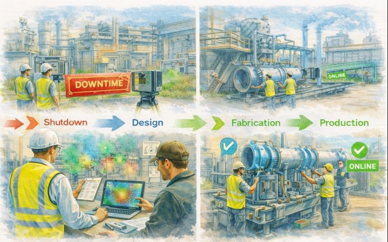
Planning the Shutdown Backwards

Successful outages are designed backwards from the installation day. FARO as-built scanning supports this process:

  1. Pre-shutdown capture โ€“ full LiDAR survey of affected areas
  2. Engineering modelling โ€“ new design built over the point cloud
  3. Workshop fabrication โ€“ components manufactured to verified geometry
  4. Dry fit digitally โ€“ clash and access checks completed
  5. On-site installation โ€“ minimal adjustment required

By the time the shutdown begins, the unknowns have been removed. Crews are executing a plan rather than solving problems in real time.

More Than Measurement

LiDAR point clouds are also powerful communication tools. Maintenance teams, project managers and contractors can visualise the work in context, improving safety and coordination. Decisions that once required multiple site visits can be made from the office with confidence.

For organisations moving toward digital twin strategies, as-built scans provide the foundation layer โ€” an accurate spatial framework that future projects can reference.

Why Every Shutdown Matters

In mining, manufacturing and energy sectors the shutdown window defines the success of the year. Budgets are tight, schedules are fixed, and tolerance for rework is zero. Engineering-led scanning recognises that reality capture is not an optional extra; it is risk management.

FARO LiDAR for as-builts delivers:

  • Reduced site hours
  • Fewer fabrication errors
  • Safer installation planning
  • Better collaboration between design and maintenance
  • Confidence that new work will integrate with old

Most importantly, it respects the fact that every shutdown matters.


Talk to Us

Hamilton By Design provides engineering-led LiDAR scanning across Sydney, the Central Coast and regional Australia, supporting brownfield upgrades, shutdown planning and reverse engineering.

If youโ€™re preparing for an outage or plant modification, speak with our team about capturing accurate as-builts before the clock starts ticking.

www.hamiltonbydesign.com.au


Why Would You 3D Scan Your Vehicle?

Engineer using a LiDAR scanner to capture 3D vehicle geometry while a client reviews point cloud data outside a workshop

Why 3D Scan Your Vehicle? Automotive 3D Scanning Explained

At first glance, 3D scanning a vehicle might sound like something reserved for manufacturers or motorsport teams. In reality, 3D vehicle scanning is becoming increasingly common for everyday automotive projects โ€” from restorations and modifications to verification, documentation, and future-proofing.

So why would someone invest in 3D scanning their vehicle? The answer is simple: accuracy, confidence, and better outcomes.


Turning a Car Into Data

A vehicle 3D scan captures millions of precise measurement points across the surface of a car or its components. This data forms a highly accurate digital model โ€” often called a point cloud โ€” which can then be used for CAD design, analysis, and fabrication.

Unlike manual measurement, 3D scanning:

  • Captures complex curves and surfaces
  • Eliminates guesswork
  • Creates a permanent digital record

Once scanned, your vehicle becomes a measurable digital asset, not just a physical object.


Engineer and client performing automotive 3D scanning of a vehicle outside a workshop using LiDAR technology

1. Reverse Engineering Parts That No Longer Exist

One of the most common reasons people scan vehicles is to recreate parts that canโ€™t be bought anymore.

This is especially relevant for:

  • Classic and vintage cars
  • Imported vehicles
  • Low-production or discontinued models

With a 3D scan, components such as panels, brackets, housings, or trims can be accurately recreated or improved โ€” without relying on worn samples or rough measurements.


2. Custom Modifications That Fit First Time

Custom automotive work only works when parts fit exactly as intended.

People scan their vehicles to design:

  • Body kits, guards, and aero components
  • Custom exhausts and mounts
  • Roll cages and chassis modifications

3D scanning allows designers and fabricators to work from real vehicle geometry, significantly reducing rework, delays, and trial-and-error fitting.


3. Vehicle Restoration and Heritage Preservation

For restoration projects, 3D scanning provides a way to capture the vehicle before changes begin.

Benefits include:

  • Preserving original geometry
  • Recording factory alignment and clearances
  • Digitally archiving rare or historically significant vehicles

This approach is particularly valuable when restoring vehicles where originality and accuracy matter.


4. Accident Damage Assessment and Verification

Not all damage is visible to the naked eye.

After an accident, 3D scanning can:

  • Detect subtle deformation
  • Compare damaged areas against original geometry
  • Provide objective measurement data

This is useful for repair planning, insurance discussions, and verifying whether a vehicle has returned to its intended shape.


5. Motorsport and Performance Development

In motorsport and performance tuning, precision is everything.

Vehicles are scanned to:

  • Analyse body shape and aerodynamics
  • Design lightweight performance components
  • Validate compliance with regulations

3D scanning shortens development cycles and allows performance improvements to be based on measured reality, not assumptions.


6. Quality Control and Build Verification

For custom builds and low-volume manufacturing, scanning provides a way to check what was built against what was designed.

This helps:

  • Verify panel alignment
  • Confirm clearances
  • Identify deviations early

Itโ€™s an objective way to ensure quality and reduce risk before a vehicle is signed off or delivered.


7. Creating a Digital Twin of Your Vehicle

Some owners choose to scan their vehicle simply to create a digital twin โ€” a complete virtual representation of the car.

A digital twin can be used for:

  • Future modifications
  • Ongoing maintenance planning
  • Design work without touching the car

Once created, it becomes a long-term reference that adds value over the vehicleโ€™s lifetime.


8. Improving Collaboration Between Trades

Vehicle projects often involve multiple parties:

  • Owners
  • Engineers
  • Designers
  • Fabricators

A 3D scan ensures everyone works from the same accurate dataset, reducing miscommunication and costly mistakes.


9. Documentation, Insurance, and Peace of Mind

A 3D scan provides:

  • Timestamped evidence of vehicle condition
  • Objective, defensible measurement data
  • Clear documentation for high-value assets

This can be useful for insurance, resale, or engineering certification.


10. Future-Proofing Your Vehicle

Once scanned:

  • The vehicle never needs to be re-measured
  • Data can be reused indefinitely
  • Modifications become easier over time

Many people scan a vehicle once, then benefit from that data for years.


Engineer and client performing vehicle 3D scanning with a car laser scanner in a coastal car park

The Real Reason People Scan Their Vehicles

People donโ€™t scan their vehicles because the technology looks impressive.

They scan them because it:

  • Saves time
  • Reduces risk
  • Improves accuracy
  • Leads to better decisions

In short:

3D scanning transforms a vehicle from something you measure repeatedly into something you understand completely.


Name
Would you like us to arrange a phone consultation for you?
Address

Automotive 3D Scanner Technology: From Cars to Complete Vehicle Digitisation

Engineer using an automotive LiDAR scanner to capture 3D vehicle geometry while a client reviews point cloud data

Automotive 3D Scanner Technology | Vehicle & Car Laser Scanning

The automotive industry has always pushed the limits of precision. From body panels and chassis alignment to aftermarket modifications and reverse engineering, accuracy is everything. This is where the automotive 3D scanner has moved from a niche tool to an essential part of modern automotive workflows.

Whether youโ€™re restoring classic vehicles, developing custom components, or validating manufacturing tolerances, 3D scanning of vehicles is now the fastest and most reliable way to capture real-world geometry.


Why Automotive 3D Scanning Matters

Traditional vehicle measurement methods โ€” tape measures, calipers, and manual templates โ€” are slow, subjective, and prone to error. In contrast, vehicle 3D scanning captures millions of data points in minutes, creating a precise digital replica of a car or component.

This digital data can be used for:

  • Reverse engineering parts
  • CAD modelling and redesign
  • Fitment verification
  • Quality control
  • Digital archiving of rare or legacy vehicles

For automotive professionals, accuracy is no longer optional โ€” itโ€™s a competitive advantage.


Engineer and client performing vehicle 3D scanning with a car laser scanner in a coastal car park

What Is a 3D Scanner for Automotive Applications?

A 3D scanner for automotive use is a device that captures the exact shape and dimensions of a vehicle or its components using laser or structured light technology. The result is a highly accurate point cloud or mesh that can be converted into CAD models.

Common scanner types include:

  • Laser-based scanners
  • Structured light scanners
  • Handheld and tripod-mounted systems

For industrial and engineering use, the car laser scanner remains the preferred option due to its accuracy, repeatability, and ability to scan reflective or complex surfaces.


Automotive Use Cases for 3D Scanning

1. 3D Scanning of Vehicle Bodies

Full 3D scanning of vehicle exteriors allows teams to:

  • Capture exact body geometry
  • Design aerodynamic add-ons
  • Validate panel alignment
  • Reproduce damaged or unavailable parts

This is particularly valuable for motorsport, restoration, and custom fabrication projects.


2. 3D Scanner for Cars in Restoration & Classic Vehicles

When original drawings no longer exist, a 3D scanner for cars becomes the only way to accurately reproduce parts.

Applications include:

  • Recreating discontinued components
  • Digitally preserving rare vehicles
  • Designing upgrades without altering originality

3. Automotive Laser Scanning for Manufacturing

In production and fabrication environments, laser scanner automotive systems are used to:

  • Verify tolerances
  • Compare as-built vehicles to CAD
  • Detect deformation or misalignment
  • Reduce rework and scrap

This level of insight is impossible with manual inspection alone.


Choosing the Best 3D Scanner for Automotive Work

Selecting the best 3D scanner for automotive use depends on accuracy requirements, environment, and workflow integration.

Key factors to consider:

  • Accuracy & resolution (sub-millimetre for engineering)
  • Speed of capture
  • Ability to scan reflective surfaces
  • Compatibility with CAD software
  • Portability for workshop or site use

For engineering-grade outcomes, tripod-mounted or hybrid systems often outperform consumer-level handheld devices.


Car Laser Scanner vs Traditional Measurement

A car laser scanner provides several advantages over conventional measurement methods:

Traditional MeasurementAutomotive 3D Scanning
Manual & subjectiveObjective & repeatable
Limited reference pointsMillions of data points
Time-consumingRapid capture
Difficult to archivePermanent digital record

This is why 3D scanning of vehicle geometry is now standard practice in high-value automotive work.


Integrating 3D Scanning Into Automotive Design

Once scanning is complete, the data feeds directly into:

  • CAD design
  • Simulation & analysis
  • Fitment studies
  • Manufacturing workflows

This scan-to-CAD process allows engineers and designers to work from reality, not assumptions.


Automotive 3D Scanning for the Future

As vehicles become more complex โ€” electric drivetrains, lightweight materials, tighter tolerances โ€” vehicle 3D scanning will continue to grow in importance.

Future applications include:

  • Digital twins of vehicles
  • Predictive maintenance modelling
  • AI-driven quality control
  • Automated inspection systems

What was once cutting-edge is now becoming standard practice.


Final Thoughts

An automotive 3D scanner is no longer just a tool for specialists โ€” itโ€™s a foundational technology for modern automotive design, fabrication, and verification.

Whether youโ€™re selecting the best 3D scanner for automotive work, implementing laser scanner automotive systems in production, or using 3D scanning of vehicle geometry for restoration and reverse engineering, the benefits are clear:

  • Higher accuracy
  • Faster workflows
  • Reduced risk
  • Better outcomes

In an industry where millimetres matter, 3D scanning of vehicles delivers confidence โ€” from concept to completion.

Name
Would you like us to arrange a phone consultation for you?
Address

The Real-World Accuracy of 3D LiDAR Scanning With FARO S150 & S350 Scanners

When people first explore 3D LiDAR scanning, one of the most eye-catching numbers in any product brochure is the advertised accuracy. FAROโ€™s Focus S150 and S350 scanners are often promoted as delivering โ€œยฑ1 mm accuracy,โ€ which sounds definitive and easy to rely on for engineering, mining and fabrication work. But anyone who has spent time working with 3D LiDAR scanning in real industrial environments understands that accuracy isnโ€™t a single number โ€” it is a system of interrelated factors.

This article explains what the ยฑ1 mm specification from FARO really means, how accuracy shifts with distance, and what engineers, project managers and clients need to do to achieve dependable results when applying 3D LiDAR scanning on live sites.


Infographic explaining 3D LiDAR scanning accuracy, showing a scanner capturing a building and highlighting factors that affect accuracy such as temperature, atmospheric noise, surface reflectivity and tripod stability. Includes diagrams comparing realistic versus unrealistic ยฑ1 mm accuracy, the impact of distance, environment and registration quality, and notes that large open sites typically achieve ยฑ3โ€“6 mm global accuracy.

1. What FAROโ€™s โ€œยฑ1 mm Accuracyโ€ Really Means in 3D LiDAR Scanning

The ยฑ1 mm number applies only to the internal distance measurement unit inside the scanner. It reflects how accurately the laser measures a single distance in controlled conditions.

It does not guarantee:

  • ยฑ1 mm for every point in a full plant model
  • ยฑ1 mm for every dimension extracted for engineering
  • ยฑ1 mm global accuracy across large multi-scan datasets

In 3D LiDAR scanning, ranging accuracy is just one ingredient. Real-world accuracy is shaped by distance, reflectivity, scan geometry and how multiple scans are registered together.


2. How Accuracy Changes With Distance in Real Projects

Even though the S150 and S350 list the same ranging accuracy, their 3D LiDAR scanning performance changes as distance increases. This is due to beam divergence, angular error, environment and surface reflectivity.

Typical real-world behaviour:

  • 0โ€“10 m: extremely precise, often sub-millimetre
  • 10โ€“25 m: excellent for engineering work, only slight noise increase
  • 25โ€“50 m: more noticeable noise and increasing angular error
  • 50โ€“100 m: atmospheric distortion and reduced overlap become evident
  • Near maximum range: still useful for mapping conveyors, yards and structures, but not suitable for tight fabrication tolerances

This distance-based behaviour is one of the most important truths to understand about 3D LiDAR scanning in field conditions.


3. Ranging Accuracy vs Positional Accuracy vs Global Accuracy

Anyone planning a project involving 3D LiDAR scanning must distinguish between:

Ranging Accuracy

The ยฑ1 mm value โ€” only the distance measurement.

3D Positional Accuracy

The true X/Y/Z location of a point relative to the scanner.

Global Point Cloud Accuracy

How accurate the entire dataset is after registration.

Global accuracy is the number engineers depend on, and it is normally around ยฑ3โ€“6 mm for large industrial sites โ€” completely normal for terrestrial 3D LiDAR scanning.


4. What Real Field Testing Reveals About FARO S-Series Accuracy

Independent practitioners across mining, infrastructure, CHPPs, plants and structural environments report similar results when validating 3D LiDAR scanning against survey control:

  • ยฑ2โ€“3 mm accuracy in compact plant rooms
  • ยฑ5โ€“10 mm across large facilities
  • Greater drift across long, open, feature-poor areas

These outcomes are not equipment faults โ€” they are the natural result of how 3D LiDAR scanning behaves in open, uncontrolled outdoor environments.


5. Why Registration Matters More Than the Scanner Model

Most real-world error in 3D LiDAR scanning comes from registration, not the laser itself.

Cloud-to-Cloud Registration

Good for dense areas, less reliable for long straight conveyors, open yards or tanks.

Target-Based Registration

Essential for high-precision engineering work.
Allows tie-in to survey control and dramatically improves global accuracy.

If your project needs ยฑ2โ€“3 mm globally, target control is mandatory in all 3D LiDAR scanning workflows.


6. Surface Reflectivity and Environmental Effects

Reflectivity dramatically affects measurement quality during 3D LiDAR scanning:

  • Matte steel and concrete return excellent data
  • Rusted surfaces return good data
  • Dark rubber, black plastics and wet surfaces reduce accuracy
  • Stainless steel and glass behave unpredictably

Environmental factors โ€” wind, heat shimmer, dust, rain โ€” also reduce accuracy. Early morning or late afternoon typically produce better 3D LiDAR scanning results on mining and industrial sites.


7. When ยฑ1 mm Is Actually Achievable

True ยฑ1 mm accuracy in 3D LiDAR scanning is realistic when:

  • Working within 10โ€“15 m
  • Surfaces are matte and reflective
  • Registration uses targets
  • Tripod stability is high
  • Conditions are controlled

This makes it suitable for:

  • Pump rooms
  • Valve skids
  • Structural baseplates
  • Reverse engineering
  • Small mechanical upgrades

But achieving ยฑ1 mm across a full plant, CHPP, or yard is outside the capability of any terrestrial 3D LiDAR scanning workflow.


8. S150 vs S350: Which One for Your Accuracy Needs?

S150 โ€“ Engineering-Focused Precision

Ideal for industrial rooms, skids, structural steel and retrofit design work where short-to-mid-range accuracy is essential.

S350 โ€“ Large-Area Coverage

Perfect for conveyors, rail lines, yards, and outdoor infrastructure.
Global accuracy must be survey-controlled for tight tolerances.

Both scanners deliver excellent 3D LiDAR scanning performance, but the S150 is the engineering favourite while the S350 is the large-site specialist.


9. What to Specify in Contracts to Avoid Misunderstandings

Instead of stating:

โ€œScanner accuracy ยฑ1 mm.โ€

Specify:

  • Local accuracy requirement (e.g., ยฑ2 mm at 15 m)
  • Global accuracy requirement (e.g., ยฑ5 mm total dataset)
  • Registration method (mandatory target control)
  • Environmental constraints
  • Verification method (e.g., independent survey checks)

This ensures everyone understands what 3D LiDAR scanning will realistically deliver.


10. When a Terrestrial Scanner Is Not Enough

Do not rely solely on 3D LiDAR scanning for:

  • Machine alignment <1 mm
  • Bearing or gearbox placement
  • Certified dimensional inspection
  • Metrology-level tolerances

In these cases, supplement scanning with:

  • Laser trackers
  • Total stations
  • Metrology arms
  • Hybrid workflows

Conclusion: The Real Truth About 3D LiDAR Scanning Accuracy

FAROโ€™s S150 and S350 are outstanding tools for industrial 3D LiDAR scanning, but the ยฑ1 mm spec does not tell the full story. Real-world accuracy is a combination of:

  • Distance
  • Registration method
  • Surface reflectivity
  • Site conditions
  • Workflow discipline

When used correctly, these scanners consistently deliver high-quality, engineering-grade point clouds suitable for clash detection, retrofit design, fabrication planning and as-built documentation.

3D LiDAR scanning is not just a laser โ€” it is an entire measurement system.
And when the system is applied with care, it produces reliable, repeatable data that reduces rework, improves safety, and strengthens decision-making across mining, construction, fabrication and industrial operations.

Where Is your project

3D Scanning Sydney CBD3D Scanning Brisbane CBD
3D Scanning across Melbourne3D Scanning across Perth
3D Scanning across Adelaide3D Scanning in The Hunter Valley
3D Scanning Mount Isa3D Scanning Emerald
3D Laser Scanning Central Coast3D Scanning in The Pilbara
3d Scanning other Areas of Australia3D Scanning Outside Australia
Hamilton By Design logo displayed on a blue tilted rectangle with a grey gradient background
Name
Address
You would like to:

3D CAD Modelling | 3D Scanning

3D Experience Platform Login

3D Scanning for Construction

Transforming Projects with 3D Scanning

3D LiDAR Scanning โ€“ Digital Quality Assurance

3D Laser Scanning and CAD Modelling Services | Hamilton By Design


There are two things weโ€™ve always believed at Hamilton By Design:

  1. Accuracy matters.
  2. If you can model it before you make it, do it.

Thatโ€™s why when the FARO Focus S70 hit the scene in 2017, we were early to the party โ€” not just because it was shiny and new (though it was), but because we knew it would change how we support our clients in mining, processing, and manufacturing environments.

The S70 didnโ€™t just give us a tool โ€” it gave us a superpower: the ability to see an entire site, down to the bolt heads and pipe supports, in full 3D before anyone picked up a wrench. Dust, heat, poor lighting โ€” no problem. With its IP54 rating and extended temperature range, this scanner thrives where other tools tap out.

And weโ€™ve been putting it to work ever since.

3D laser scan of mechanical plant

โ€œMeasure Twice, Cut Onceโ€ Just Got a Whole Lot More Real

Laser scanning means we no longer rely on outdated drawings, forgotten markups, or that sketch someone did on the back of a clipboard in 2004.

Weโ€™re capturing site geometry down to millimetres, mapping full plant rooms, structural steel, conveyors, tanks, ducts โ€” you name it. And the moment we leave site, weโ€™ve already got the data we need, registered and ready to drop into SolidWorks.

Which, by the way, weโ€™ve been using since 2001.

Yes โ€” long before CAD was cool, we were deep into SolidWorks building models, simulating loads, tweaking fit-ups, and designing smarter mechanical solutions for complex environments. Itโ€™s the other half of the story โ€” scan it, then model it, all in-house, all under one roof.

Safety by Design โ€“ Literally

Hereโ€™s the part people often overlook: 3D laser scanning isnโ€™t just about accuracy โ€” itโ€™s about safety.

Weโ€™ve worked across enough plants and mine sites to know that the real hazards are often the things you donโ€™t see in a drawing. Tight access ways. Awkward pipe routing. Obstructions waiting to drop something nasty when a shutdown rolls around.

By scanning and reviewing environments virtually, we can spot those risks early โ€” hazard identification before boots are even on the ground. We help clients:

  • Reduce time-on-site
  • Limit the number of field visits
  • Minimise exposure to high-risk zones
  • Plan safer shutdowns and installations

Thatโ€™s a big win in any plant or processing facility โ€” not just for compliance, but for peace of mind.

SolidWorks 3D Modelling
CAD model from site scan

From Point Cloud to Problem Solved

Since 2017, our scanning and modelling workflows have supported:

  • Brownfield upgrade projects
  • Reverse engineering of legacy components
  • Fabrication and installation validation
  • Creation of digital twins
  • Asset audits and documentation updates

And when you pair that with 24 years of SolidWorks expertise, you get more than just a pretty point cloud โ€” you get practical, buildable, fit-for-purpose engineering solutions backed by deep industry knowledge.


Thinking about your next project? Letโ€™s make it smarter from the start.

Weโ€™ll scan it, model it, and engineer it as we have been doing for decades โ€” with zero guesswork and full confidence.

Hamilton By Design logo displayed on a blue tilted rectangle with a grey gradient background

www.hamiltonbydesign.com.au


Mechanical Engineering | Structural Engineering

Mechanical Drafting | Structural Drafting

3D CAD Modelling | 3D Scanning

Our clients:

Name
Would you like us to arrange a phone consultation for you?
Address