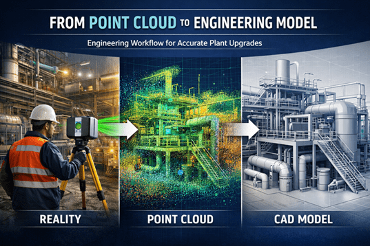
Modern industrial facilities—especially in mining, processing plants, and heavy infrastructure—are complex environments where accurate site information is essential. Before engineers can design upgrades, modifications, or shutdown works, they must understand exactly what exists in the field today.
This is where the point cloud to engineering model workflow becomes critical.
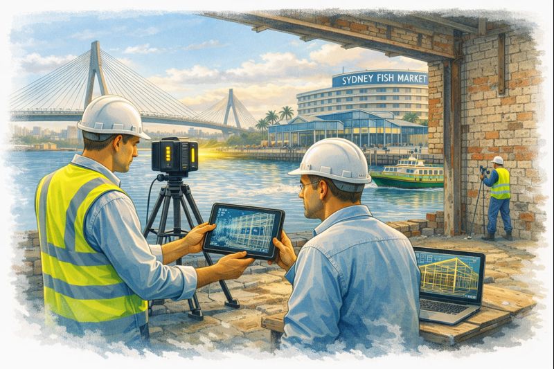
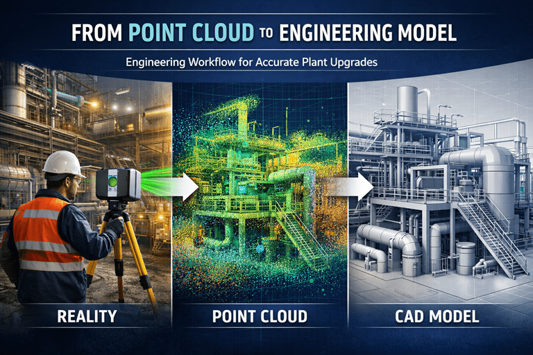
Using engineering-grade 3D laser scanning, engineers can capture millions of spatial measurements in minutes, creating a highly accurate digital representation of existing plant conditions. These measurements form what is known as a point cloud, which becomes the foundation for accurate CAD models, engineering design, and upgrade planning.
Hamilton By Design specialises in this process through engineering-grade reality capture and modelling services across mining and industrial facilities.
Learn more about our scanning services here:
https://www.hamiltonbydesign.com.au/home/engineering-grade-3d-laser-scanning-mining-industrial/
What is a Point Cloud?
A point cloud is a dense collection of spatial coordinates captured by a 3D laser scanner. Each point represents a precise location on a surface such as steelwork, piping, equipment, or structures.
Modern scanners can capture millions of points per second, creating a digital snapshot of the real environment with millimetre-level accuracy.
Once captured, the point cloud becomes the digital foundation used by engineers to reconstruct existing plant geometry.

The Point Cloud to Engineering Model Workflow
Turning raw scan data into usable engineering information involves several structured steps.
1. Project Planning and Site Preparation
Before scanning begins, engineers define:
- Required accuracy
- Project scope
- Areas to be captured
- Level of modelling detail required
This ensures the captured data supports downstream engineering tasks such as pipe routing, structural modifications, or equipment installations.
If you are planning a plant modification or shutdown project, capturing accurate field conditions early is essential.
Related article:
https://www.hamiltonbydesign.com.au/capture-existing-conditions-before-plant-upgrades/
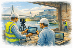
2. Laser Scanning and Data Capture
During the field phase, laser scanners are positioned throughout the facility to capture overlapping scans of the plant.
Typical captured elements include:
- Structural steel
- Pipework
- Mechanical equipment
- Cable trays
- Platforms and access ways
- Tanks and vessels
Each scan records millions of measurements to create a complete 3D dataset of the site.
3. Scan Registration and Point Cloud Processing
After scanning, the raw scans must be processed. This includes:
- Aligning multiple scans together (registration)
- Removing noise or unwanted points
- Optimising the dataset for modelling
This processing stage converts raw scan files into a coherent, usable point cloud model ready for engineering analysis.
4. Importing the Point Cloud into CAD Software
Once processed, the point cloud is imported into engineering software such as:
- SolidWorks
- AutoCAD
- Revit
- Plant design platforms
Within the design environment, the point cloud becomes a reference model that accurately represents real-world conditions. Engineers can rotate, section, and inspect the data to understand plant geometry before any design begins.
5. Engineering Model Creation
Using the point cloud as a guide, engineers begin creating intelligent CAD models of plant assets.
Typical modelling tasks include:
- Pipe routing and spool modelling
- Structural steel modelling
- Equipment placement
- Conveyor and mechanical system modelling
- Access platforms and maintenance areas
The result is a clean engineering model derived directly from the scanned environment.
This process converts raw spatial data into parametric engineering objects, enabling design teams to work with accurate plant geometry.
6. Design Coordination and Clash Detection
Once the engineering model exists, it becomes a powerful tool for project planning.
Engineers can:
- Test upgrade concepts
- Perform clash detection
- Evaluate maintenance access
- Design shutdown modifications
- Prepare fabrication drawings
Because the model reflects real site conditions, design errors and rework can be significantly reduced.
Why This Workflow Matters in Mining and Industrial Projects
Mining plants and processing facilities often evolve over decades. Drawings may be outdated, incomplete, or inaccurate.
Laser scanning solves this problem by capturing what actually exists today, not what legacy drawings suggest.
Benefits include:
- Reduced design risk
- Accurate retrofit engineering
- Faster shutdown planning
- Better contractor coordination
- Improved safety planning
Point cloud modelling also allows engineers to handle complex plant geometries that would be difficult to measure manually.
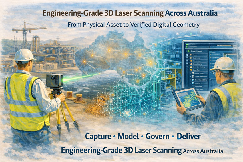
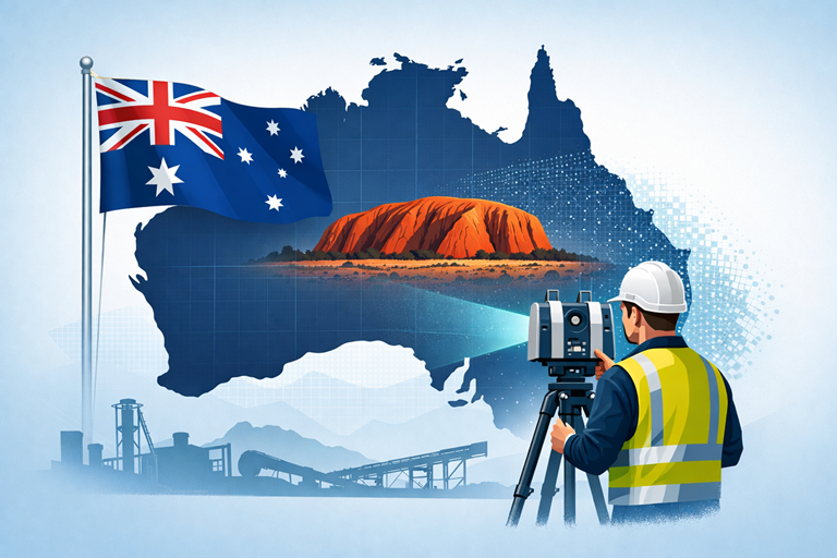
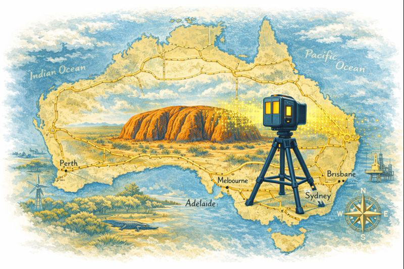
3D Laser Scanning Across Australia
Hamilton By Design provides engineering-grade 3D laser scanning services across Australia, supporting mining operations, processing plants, and industrial facilities.
Our workflow focuses on delivering engineering-ready models, not just scan data.
Learn more here:
https://www.hamiltonbydesign.com.au/home/engineering-services/3d-laser-scanning/3d-laser-scanning-across-australia/
From Reality Capture to Engineering Insight
The transition from point cloud to engineering model is more than a technical workflow—it is the bridge between physical infrastructure and digital engineering design.
By combining precise laser scanning with engineering modelling expertise, projects can move forward with confidence, knowing that designs are based on accurate site conditions.
At Hamilton By Design, we specialise in helping industrial operators convert reality capture into practical engineering outcomes for plant upgrades, shutdowns, and infrastructure projects.
If you would like to discuss how point cloud modelling can support your next project, explore our engineering scanning services here: