Engineering Lessons from Recent Media: Foundations & Process First
A recent Tasmanian news story reported on a homeowner receiving a substantial payout after major renovations led to cracking in their house. The coverage in The Mercury described how the problems were linked to inadequate consideration of existing footings and ground conditions during the design of a second-storey extension:
Woodbridge homeowner wins huge payout after home cracked following two-storey extension
https://www.themercury.com.au/truecrimeaustralia/police-courts-tasmania/woodbridge-homeowner-wins-huge-payout-after-home-cracked-following-twostorey-extension
Legal industry commentators also discussed the same matter as a reminder of professional responsibilities when working on existing buildings:
Cracks in the duty: When engineers miss the foundations – Barry Nilsson Lawyers
https://bnlaw.com.au/knowledge-hub/insights/cracks-in-the-duty-when-engineers-miss-the-foundations/
Rather than revisiting who was right or wrong, the reporting offers a constructive opportunity to reflect on how everyday engineering processes can be improved—especially on renovation and brownfield projects where information is incomplete.
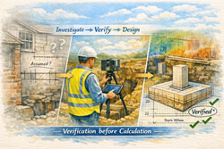
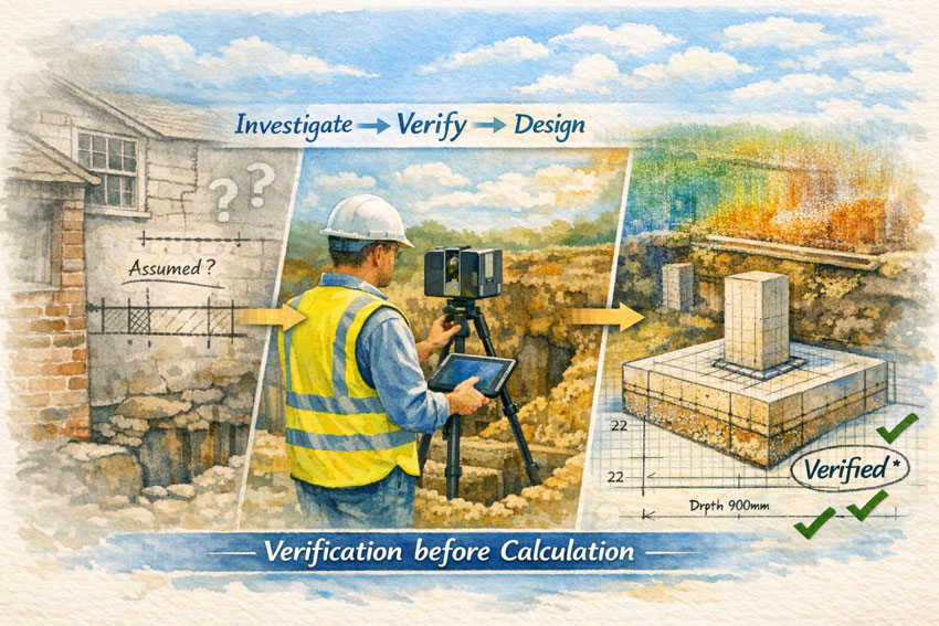
1. Investigation Is Part of Design
The media narrative highlights a simple truth:
when we work with existing structures, the ground and foundations are not background details—they are primary design inputs.
Good practice means:
- Treating site verification as a formal stage of the project
- Making recommendations for geotechnical or structural checks early
- Being clear about what is known and what is assumed
A design based only on drawings is never as reliable as one based on verified conditions.
2. Make Assumptions Visible
News coverage often shows that problems grow in the grey space between architect, engineer, and builder.
Helpful habits include:
- Keeping an assumptions register shared by the whole team
- Noting on drawings what has been confirmed on site
- Setting clear triggers for further investigation
When assumptions have owners, risks have boundaries.
3. Communication Is a Structural Element
Many reported disputes stem less from technical ability and more from gaps in communication.
Engineers can lead by:
- Discussing uncertainties openly at the start
- Confirming decisions in writing after meetings
- Encouraging contractors to report unexpected conditions
Good communication is often cheaper than remediation.
4. Scope Changes = Risk Changes
Renovations rarely stay the same as the first sketch.
Media accounts of failures frequently involve projects that grew beyond the original intent.
Better process includes:
- Re-checking engineering scope whenever the design evolves
- Linking approvals to stages of investigation
- Pricing verification as a real deliverable, not an afterthought
Clarity of scope is a form of structural strength.
5. Document the Story of the Project
Journalists and lawyers both rely on records to understand what happened.
For engineers, simple steps make a big difference:
- Photos tied to inspection notes
- Short design basis statements
- Emails confirming client instructions
- Sketches of as-found conditions
Documentation is not defensive—it is professional memory.
6. Respect the Interface Between Old and New
The media coverage repeatedly points to the moment where new work met an older structure.
That interface is where uncertainty lives.
Practical responses:
- Specific checks on existing footings before adding load
- Independent review for heritage or unknown construction
- Monitoring after completion to confirm behaviour
The junction between old and new deserves the most attention.
7. The Courage to Pause
Perhaps the most human lesson from the reports is that engineers sometimes need to slow a project down.
Saying:
“We need more information before proceeding”
is not obstruction—it is professionalism.
Organisations that support this courage protect clients and engineers alike.
Turning Headlines into Better Practice
The story covered by The Mercury and the subsequent industry commentary do not need to be read as cautionary tales. They can be read as learning opportunities:
- Investigate before you calculate
- Make assumptions visible
- Communicate uncertainty early
- Document decisions clearly
- Treat existing conditions with respect
These are the foundations of good engineering, long before concrete is poured.
Final Thought
Risk will always exist in renovation and brownfield work.
What we control is the process we wrap around that risk.
When engineers focus on verification, transparency, and collaboration, projects become safer, clients are better served, and the profession grows stronger.
Good engineering is not only about correct numbers—
it is about asking the right questions at the right time.
References
“Woodbridge homeowner wins huge payout after home cracked following two-storey extension” — The Mercury (Tasmania)
🔗 https://www.themercury.com.au/truecrimeaustralia/police-courts-tasmania/woodbridge-homeowner-wins-huge-payout-after-home-cracked-following-twostorey-extension/news-story/32fe411a57c2471be44962cba86100bd