

Clear, reliable engineering decisions
Hamilton by Design provides end-to-end Finite Element Analysis (FEA) to help you validate designs, reduce risk, and move faster. We handle quick checks through to complex non-linear and dynamic studies—explained in plain English and backed by solid engineering.

What we do (not limited to)
Core FEA
- Linear static stress for parts and assemblies
- Time-based motion / kinematic analysis
Advanced (Simulation Professional level)
- Fatigue (constant & variable amplitude)
- Modal (resonant frequency) and buckling
- Steady-state and transient thermal
- Drop-test and impact
- Pressure vessel assessment
- Topology optimization
- Submodeling and load-case management
Specialist (Simulation Premium level)
- Non-linear statics: plasticity, hyperelastic materials, large deflection, complex contact
- Non-linear dynamics: rate-dependent behaviour, contact events
- Linear dynamics: time history, harmonic response, random vibration, response spectrum
- Composite laminate analysis: ply-by-ply results, Tsai-Hill / Tsai-Wu failure
Typical outputs
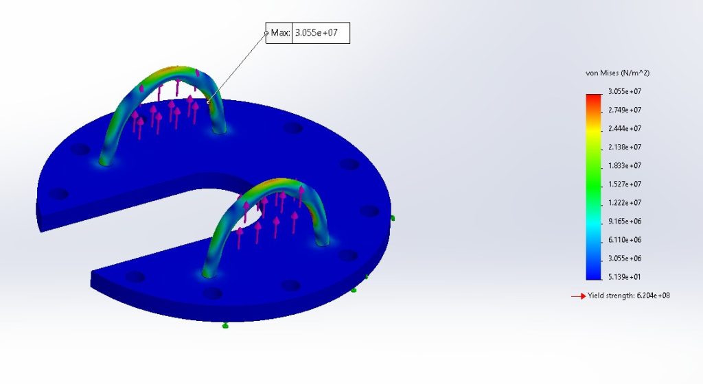
- Stress/strain maps (von Mises, principal, safety factors)
- Deflection and stiffness results (linear and large-deflection)
- Modes and vibration responses (harmonic, random)
- Fatigue life and damage accumulation
- Thermal distributions and heat-flow
- Clear pass/fail against your acceptance criteria
How we work
- Scope & assumptions – Define loads, constraints, materials, and success criteria.
- Model prep & meshing – Clean geometry, set contact strategy, plan mesh convergence.
- Simulation & calibration – Run studies with sensitivity checks; refine as needed.
- Validation & reporting – Concise report, native files, and practical design recommendations.
Who we support
Industrial equipment • Aerospace • Defense & robotics • Marine & offshore • Energy & thermal systems • Consumer products


Toolchain
SOLIDWORKS® 3D CAD Premium with SOLIDWORKS Simulation Professional & Simulation Premium add-ins.
Engagement options
- NDA-friendly
- Fixed-price or time & materials
- Rapid turnaround available
Get in touch
Email: sales@hamiltonbydesign.com.au
Location: Australia (AEST)
Mechanical Engineering | Structural Engineering
Mechanical Drafting | Structural Drafting
3D Laser Scanning | 3D CAD Modelling | 3D Scanning