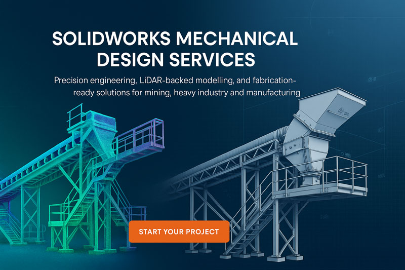
SolidWorks Design Services
The Many Faces of Mechanical Design: How SolidWorks Powers Modern Engineering Across Australia
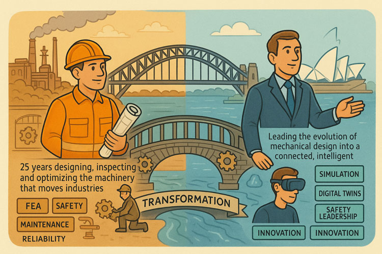
At Hamilton By Design, we see the same pattern every day across mining, heavy industry, manufacturing, and complex brownfield environments: the quality of engineering outcomes depends directly on the quality of the models driving them. And when it comes to mechanical design, SolidWorks remains one of the most capable and versatile platforms on the planet.
From dragline components to sheet metal enclosures, from pressure vessel upgrades to bespoke robotics, SolidWorks enables engineers to turn ideas into precise, fabrication-ready models that reduce rework, eliminate uncertainty, and accelerate project delivery.
Below, we explore the full spectrum of mechanical design disciplines where SolidWorks excels — and how Hamilton By Design uses this capability to deliver accurate, reliable, engineering-grade outcomes across Australia.
Why SolidWorks Remains the Backbone of Mechanical Design
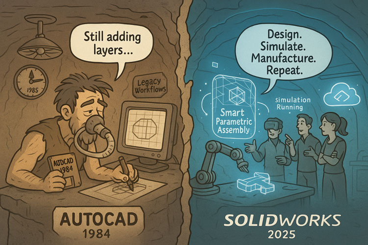
SolidWorks brings together parametric modelling, simulation, large assembly performance, surfacing, sheet metal tools, weldments, routing and visualisation under a single environment. The result is powerful:
✔ Engineering that is data-driven
✔ Models that are precise and fabrication-ready
✔ Assemblies that reflect true site conditions
✔ Designs that respond intelligently to changes
✔ Drawings that follow Australian Standards
✔ Seamless integration with LiDAR-based as-builts
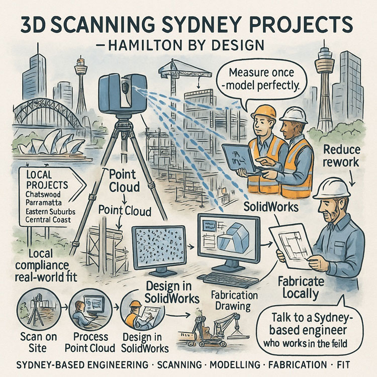
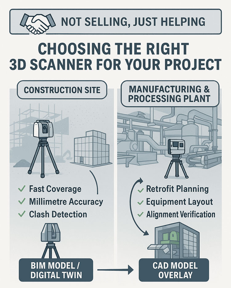
When paired with Hamilton By Design’s LiDAR scanning workflows, SolidWorks becomes an engine for delivering zero-guesswork mechanical design.
Mechanical Design Disciplines Perfectly Suited to SolidWorks Modelling
SolidWorks supports a huge range of engineering tasks. Below is a deep dive into the disciplines where Hamilton By Design deploys it every day.
1. Machine Design: Precision for Moving Systems
SolidWorks is a natural fit for mechanical equipment upgrades and R&D design work, including:
- Gearboxes, shafts, keys, couplings
- Linear motion systems and actuators
- Mechanical linkages, cams and levers
- Robotic mechanisms
- Safety guards, enclosures and subframes
- Automation concept development
Whether we’re modelling a drive assembly for a conveyor or designing a new piece of automated equipment, SolidWorks gives us full control over the mechanics, kinematics, clearances and manufacturability.
2. Structural Mechanical Design: Frames, Platforms & Fabrication
Mining and industrial plants rely heavily on welded structures and access systems. SolidWorks weldments excel at:
- Platforms, walkways and stair systems
- Equipment bases, skids and structural frames
- Gantries, monorails and supports
- Pipe supports and brackets
- Structural reinforcements and upgrade scopes
Built-in cut lists, profile libraries and FEA ensure every frame is practical, safe and fabrication-ready.
3. Pressure Vessels, Tanks & Piping Systems
SolidWorks is an ideal tool for pressure-bound components and interconnected plant systems:
- Tanks, vessels, bins and hoppers
- Nozzles, flanges, stiffeners and ladders
- Pipe routing and spooled sections
- Chute systems, transitions and flow paths
- Wear liners and maintenance-friendly redesigns
With stress linearisation, buckling analysis and accurate geometry import from LiDAR scans, we ensure designs meet engineering intent and fit up perfectly on site.
4. Sheet Metal: From Light Fabrication to Industrial Ducting
SolidWorks is the industry standard for sheet metal components:
- Ducting and HVAC transitions
- Guards, housings and folded enclosures
- Electrical cabinets
- Chute panels
- Laser-cut and folded brackets
Automatic flat patterns and K-factor control mean fewer mistakes at the plasma/laser cutters and more predictable outcomes for fabricators.
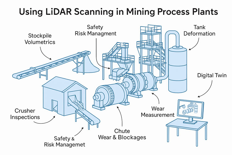
5. Heavy Industry & Mining Equipment Modelling
Hamilton By Design’s roots in mining and heavy industry make SolidWorks invaluable for:
- Conveyor components and guarding
- Diverter chutes, hoppers and flow-optimised transitions
- Bucket-wheel reclaimer parts
- Crusher and screen upgrades
- Dragline component modelling
- Structural deformation/realignment scopes
Combined with LiDAR scanning, SolidWorks becomes the tool that eliminates shutdown fit-up problems.
6. Product Design & Industrial Design
SolidWorks’ surfacing and parametric tools are ideal for:
- Consumer products
- Power tools and ergonomic items
- Injection-moulded components
- Kitchen or appliance prototypes
- Concept development for early-stage R&D
It supports rapid iterations, rendering, and export for 3D printing.
7. Robotics & Automation Systems
With the rise of automated processing and Industry 4.0, SolidWorks continues to shine in:
- End effectors
- Robotic arms and actuators
- Kinematic studies
- Sensor housings
- Concept layouts for automated cells
We frequently pair this with our LiDAR models of existing plants to create automation solutions that genuinely fit the space.
8. Tooling, Jigs & Fixtures
Fabrication and machining rely on accurate tooling, and SolidWorks helps us design:
- Welding jigs
- Machining fixtures
- Assembly tooling
- Positioning and inspection gauges
- Drill guides and alignment tooling
Parametric updates make future modifications simple and consistent.
9. Material Handling Systems
Across mining, ports, agriculture and waste facilities, SolidWorks supports:
- Conveyor layouts
- Screw and chain conveyors
- Transfer chute redesigns
- Feeders, bins and flow systems
- Skids and support structures
We routinely pair mechanical redesign with simulation, checking wear patterns, stresses and clearances.
10. Reverse Engineering & As-Built Modelling from LiDAR
This is where Hamilton By Design leads the industry.
We scan sites with millimetre-level LiDAR, then rebuild clean parametric models in SolidWorks for:
- Brownfield upgrades
- Fit-up verification
- Clash detection
- Replacements and like-for-like manufacturing
- Structural deformation assessments
- Shutdown planning
It is the combination of LiDAR + engineering + SolidWorks that gives clients complete confidence in their next project.
How Clients Benefit from SolidWorks-Driven Mechanical Design
✔ Reduced rework
✔ Faster shutdown upgrades
✔ Accurate manufacturing drawings
✔ Better communication between engineers, fabricators and site teams
✔ Safer and more predictable installations
✔ Clear, simulation-backed decision-making
From CHPPs to ports, from power stations to manufacturing plants, SolidWorks modelling allows Hamilton By Design to deliver engineering outcomes you can trust.

Partner With Hamilton By Design for SolidWorks Mechanical Design
We support clients across:
- NSW (Sydney, Newcastle, Central Coast, Hunter Valley)
- QLD (Bowen Basin, Surat Basin, Mount Isa)
- WA (Perth, Pilbara)
- SA, VIC and regional Australia
If your next project needs mechanical accuracy, design certainty or LiDAR-integrated engineering, our team is ready to support you.
Our clients