Conveyor Drives in Underground Coal Mines

Operation, Design Challenges, and the Role of Direct Drive Units
In the highly demanding and regulated world of underground coal mining, the reliable and efficient transport of coal from the mining face to the surface is critical. Among the many systems involved in this process, conveyor drives play a pivotal role. These systems are tasked with powering conveyor belts that haul coal over long distances through often confined and hazardous environments. A vital part of this setup includes the use of direct drive units (DDUs), particularly in low-profile applications such as underground operations.

This document explores the functionality of conveyor drives in underground coal mines, the unique challenges faced in their operation, the complexities design engineers encounter in their development, and the concept of the phase “outbye”—a term widely used in underground mining to describe the direction and location of operations.


Conveyor Drives in Underground Coal Mining

A conveyor drive is a mechanical system that powers conveyor belts used to transport materials, in this case, coal. In underground mines, these conveyor belts often run for several kilometers, extending from the coal face (the area where coal is actively being cut and mined) to the shaft or drift that brings the coal to the surface.

The drive systems can be located at several points along the belt:

  • Head drive: Located at the discharge end of the conveyor.
  • Tail drive: Located at the loading end.
  • Mid-belt drives: Installed partway along long conveyors to help manage torque and reduce belt tension.

In the context of underground coal mines, the term “conveyor drive” is generally associated with the head or tail drive unit, which powers the movement of the belt.


Role of Direct Drive Units (DDUs)

Direct Drive Units are electric motors directly coupled to the drive shaft of the conveyor pulley, eliminating the need for intermediary gearboxes or belt drives. These units are especially advantageous in underground mining due to their compact design, reliability, and reduced maintenance.

Benefits of DDUs in Underground Coal Mines

  1. Compact Size: Ideal for low-profile mining applications where vertical space is restricted.
  2. Energy Efficiency: With fewer mechanical components, DDUs offer less friction and mechanical losses.
  3. Lower Maintenance: No gearboxes or belt couplings to service.
  4. Increased Reliability: Fewer parts mean fewer failure points.
  5. Improved Safety: The enclosed design minimizes exposure to moving parts and flammable materials.

Australian Mining, Hamilton By Design, Mechanical Engineering

Operational Challenges of Conveyor Drives Underground

Underground coal mining presents a set of challenges not commonly encountered in surface operations. Conveyor drives, as the lifeblood of coal transportation, are central to these operational difficulties.

1. Space Constraints

Underground roadways are typically narrow and low, especially in coal seams with minimal thickness. This limitation forces the use of low-profile conveyor systems, which in turn limits the size and configuration of the drive units.

2. Dust and Moisture Exposure

Coal dust is highly abrasive and, in certain concentrations, explosive. Moisture from groundwater or the mining process further complicates the reliability of drive components. Ensuring DDUs are properly sealed and rated for these harsh conditions is critical.

3. Heat and Ventilation

Electric motors generate heat, which must be dissipated. However, underground mines have limited ventilation. Overheating can be a major issue, requiring cooling systems or specialized motor enclosures.

4. Explosion-Proof Requirements

Due to the potential presence of methane gas and coal dust, all electrical equipment, including conveyor drives, must comply with stringent explosion-proof standards (e.g., IECEx or ATEX ratings).

5. Long Haul Distances

Modern coal faces can be several kilometers from the shaft bottom. Transporting coal over long distances places mechanical stress on conveyor belts and drive units, increasing the risk of failure if not properly engineered.

6. Maintenance Access

Accessing conveyor drives for inspection or maintenance can be difficult in tight underground environments. Failures that require replacement or repair can cause significant production delays.

7. Load Variability

The volume of coal being hauled can vary significantly during a shift, which places variable demands on the drive system. The control systems must be able to accommodate fluctuating loads without mechanical strain.


Engineering and Design Challenges

Design engineers are tasked with creating conveyor drive systems that are not only robust and efficient but also compact and compliant with mining regulations. Some of the key design challenges include:

1. System Integration in Confined Spaces

Engineering a system that fits into limited space while delivering the necessary power is a fundamental challenge. Direct drive units help address this by eliminating gearboxes, but the motor itself must still be sized correctly.

2. Material Selection

Materials used must be corrosion-resistant, non-sparking, and capable of withstanding vibration, dust ingress, and moisture. This often limits design options and increases costs.

3. Thermal Management

Ensuring that the drive units do not overheat requires careful thermal modeling and the use of heat-resistant components. In some cases, passive or active cooling systems are integrated.

4. Compliance with Standards

Designs must adhere to a host of mining and electrical standards for flameproof and intrinsically safe equipment. Certification processes can be lengthy and expensive.

5. Modularity and Transportability

Since access to underground sites is limited, equipment must be modular or transportable in pieces small enough to be moved through shafts or drifts. Assembling and commissioning underground adds another layer of complexity.

6. System Control and Monitoring

Advanced drives require smart control systems that can adjust to load demands, monitor for faults, and integrate with mine-wide automation systems. Designing these systems requires interdisciplinary expertise.

7. Redundancy and Reliability Engineering

System failure underground can halt production and pose safety risks. Engineers must design for redundancy and easy switch-over between drive systems when necessary.


Understanding the Term “Outbye”

In underground mining terminology, directionality is essential for communication and logistics. The terms “inbye” and “outbye” are commonly used to describe relative directions underground.

What Does “Outbye” Mean?

  • Outbye refers to the direction away from the coal face and toward the surface or the mine entrance.
  • Conversely, inbye means toward the coal face.

For example:

  • If a miner is walking from the coal face toward the conveyor belt transfer station, they are walking outbye.
  • If a service vehicle is heading toward the longwall face, it is moving inbye.

Relevance of “Outbye” in Conveyor Systems

In conveyor operations:

  • The coal face is the inbye starting point.
  • The belt head drive and transfer points to the main conveyor system are located outbye.
  • Maintenance and service activities often take place outbye to avoid interfering with production at the face.

Understanding this term is critical for coordinating activities underground, as directions are often communicated using inbye and outbye references rather than compass points or distances.


SolidWorks 3D Experience
Hamilton By Design

Innovations and Future Trends

The mining industry continues to evolve, and conveyor drive systems are no exception. Some of the emerging trends and technologies include:

1. Variable Speed Drives (VSDs)

VSDs allow precise control over motor speed and torque, improving efficiency and reducing mechanical stress. They are increasingly paired with direct drive units to optimize performance.

2. Condition Monitoring

Sensors embedded in motors and drive systems can provide real-time feedback on vibration, temperature, and load. Predictive maintenance models reduce downtime.

3. Permanent Magnet Motors

These motors offer higher efficiency and torque density compared to traditional induction motors, making them well-suited for space-constrained environments.

4. Automation and Remote Control

Fully integrated systems that allow operators to monitor and control conveyor drives from surface control rooms are becoming standard.

5. Modular, Plug-and-Play Designs

Future drive units are being designed with ease of installation and replacement in mind, enabling faster deployment and lower maintenance impact.


Conclusion

Conveyor drive systems in underground coal mining are vital to the continuous flow of material and, by extension, the productivity of the entire mining operation. The adoption of direct drive units is helping to meet the unique demands of underground environments by providing compact, reliable, and efficient power transmission solutions.

However, these systems are not without their challenges. From the operational constraints of underground environments to the rigorous demands placed on design engineers, the development and maintenance of these systems require specialized knowledge, innovative thinking, and strict adherence to safety standards.

Moreover, understanding mining-specific terminology such as “outbye” provides important context for the deployment and maintenance of conveyor systems. As technology continues to advance, we can expect to see more intelligent, adaptive, and efficient conveyor drive systems that are better suited to the evolving demands of underground coal mining.

#CoalMining #EngineeringSolutions #MechanicalEngineering #ConveyorSystems #MiningIndustry #UndergroundMining #AustralianEngineering #HamiltonByDesign

Hamilton By Design | Mechanical Drafting | Structural Drafting | 3-D Lidar Scanning

3D Laser Scanning and CAD Modelling Services | Hamilton By Design


There are two things we’ve always believed at Hamilton By Design:

  1. Accuracy matters.
  2. If you can model it before you make it, do it.

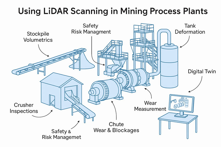
That’s why when the FARO Focus S70 hit the scene in 2017, we were early to the party — not just because it was shiny and new (though it was), but because we knew it would change how we support our clients in mining, processing, and manufacturing environments.

The S70 didn’t just give us a tool — it gave us a superpower: the ability to see an entire site, down to the bolt heads and pipe supports, in full 3D before anyone picked up a wrench. Dust, heat, poor lighting — no problem. With its IP54 rating and extended temperature range, this scanner thrives where other tools tap out.

And we’ve been putting it to work ever since.

3D laser scan of mechanical plant

“Measure Twice, Cut Once” Just Got a Whole Lot More Real

Laser scanning means we no longer rely on outdated drawings, forgotten markups, or that sketch someone did on the back of a clipboard in 2004.

We’re capturing site geometry down to millimetres, mapping full plant rooms, structural steel, conveyors, tanks, ducts — you name it. And the moment we leave site, we’ve already got the data we need, registered and ready to drop into SolidWorks.

Which, by the way, we’ve been using since 2001.

Yes — long before CAD was cool, we were deep into SolidWorks building models, simulating loads, tweaking fit-ups, and designing smarter mechanical solutions for complex environments. It’s the other half of the story — scan it, then model it, all in-house, all under one roof.

Safety by Design – Literally

Here’s the part people often overlook: 3D laser scanning isn’t just about accuracy — it’s about safety.

We’ve worked across enough plants and mine sites to know that the real hazards are often the things you don’t see in a drawing. Tight access ways. Awkward pipe routing. Obstructions waiting to drop something nasty when a shutdown rolls around.

By scanning and reviewing environments virtually, we can spot those risks early — hazard identification before boots are even on the ground. We help clients:

  • Reduce time-on-site
  • Limit the number of field visits
  • Minimise exposure to high-risk zones
  • Plan safer shutdowns and installations

That’s a big win in any plant or processing facility — not just for compliance, but for peace of mind.

SolidWorks 3D Modelling
CAD model from site scan

From Point Cloud to Problem Solved

Since 2017, our scanning and modelling workflows have supported:

  • Brownfield upgrade projects
  • Reverse engineering of legacy components
  • Fabrication and installation validation
  • Creation of digital twins
  • Asset audits and documentation updates

And when you pair that with 24 years of SolidWorks expertise, you get more than just a pretty point cloud — you get practical, buildable, fit-for-purpose engineering solutions backed by deep industry knowledge.


Thinking about your next project? Let’s make it smarter from the start.

We’ll scan it, model it, and engineer it as we have been doing for decades — with zero guesswork and full confidence.

📍 www.hamiltonbydesign.com.au


Mechanical Engineering | Structural Engineering

Mechanical Drafting | Structural Drafting

3D CAD Modelling | 3D Scanning

Simplify Engineering Scan it Design it

Hamilton By Design

3D Cad Design | 3D Modelling | 3D Laser Scanning | Local Scanning

3D Scanning Brisbane | 3D Scanning Perth | 3D Scanning Melbourne

Laser scanning Central Coast

Laser Scanning for Engineering

SolidWorks | SolidWorks CAD Design | SolidWorks Mechanical Design

SolidWorks Structural Design | SolidWorks Smart Structures

3D Modelling 

SolidWorks 3D Modelling

 By Hamilton By Design | www.hamiltonbydesign.com.au

In the 1980s through to the early 2000s, AutoCAD ruled supreme. It revolutionised the way engineers and designers approached 2D drafting, enabling technical drawings to be created and shared with speed and precision across industries. For two decades, it set the benchmark for visual communication in engineering and construction. But that era has passed.

Today, we live and work in a three-dimensional world — not only in reality, but in design.

From 2D Drafting to Solid Modelling: The New Standard

At Hamilton By Design, we see 3D modelling not just as a tool, but as an essential evolution in how we think, design, and manufacture. The transition from 2D lines to solid geometry has reshaped the possibilities for every engineer, machinist, and fabricator.

With the widespread adoption of platforms like SolidWorks, design engineers now routinely conduct simulations, tolerance analysis, motion studies, and stress testing — all in a virtual space before a single part is made. Companies like TeslaFordEatonMedtronic, and Johnson & Johnson have integrated 3D CAD tools into their product development cycles with great success, dramatically reducing rework, increasing precision, and accelerating innovation.

Where 2D design was once enough, now solid models drive machininglaser cutting3D printingautomated manufacturing, and finite element analysis (FEA) — all from a single digital source.

A Growing Ecosystem of Engineering Capability

It’s not just the software giants making waves — a global network of specialised engineering services is helping bring 3D design to life. Companies like Rishabh EngineeringShalin DesignsCAD/CAM Services Inc.Archdraw Outsourcing, and TrueCADD provide design and modelling support to projects around the world.

At Hamilton By Design, we work with and alongside these firms — and others — to deliver scalable, intelligent 3D modelling solutions to the Australian industrial sector. From laser scanning and site capture to custom steel fabrication, we translate concepts into actionable, manufacturable designs. Our clients benefit not only from our hands-on trade knowledge but also from our investment in cutting-edge tools and engineering platforms.

So What’s Next? The Future Feels More Fluid Than Solid

With all these tools now at our fingertips — FEA simulation, LiDAR scanning, parametric modelling, cloud collaboration — the question becomes: what comes after 3D?

We’ve moved from pencil to pixel, from 2D lines to intelligent digital twins. But now the line between design and experience is beginning to blur. Augmented reality (AR), generative AI design, and real-time simulation environments suggest that the next wave may feel more fluid than solid — more organic than mechanical.

We’re already seeing early glimpses of this future:

  • Generative design tools that evolve geometry based on performance goals
  • Real-time digital twins updating with sensor data from operating plants
  • AI-driven automation that simplifies design iterations in minutes, not days

In short: the future of 3D design might not be “3D” at all in the traditional sense — it could be interactive, immersive, adaptive.

At Hamilton By Design — We’re With You Now and Into the Future

Whether you’re looking to upgrade legacy 2D drawings, implement laser-accurate reverse engineering, or develop a full-scale 3D model for simulation or manufacturing — Hamilton By Design is here to help.

We bring hands-on trade experience as fitters, machinists, and designers, and combine it with the modern toolset of a full-service mechanical engineering consultancy. We’re not just imagining the future of design — we’re building it.

Let’s design smarter. Let’s think in 3D — and beyond.

Contact Us
🌐 

www.hamiltonbydesign.com.au
✉️ anthony@hamiltonbydesign.com.au📞 0477 002 249By Hamilton By Design | www.hamiltonbydesign.com.au

Bulk Materials Conveyor Transfer

Designing reliable bulk materials conveyor transfer station chutes involves a careful consideration of various principles to ensure efficient material handling, minimize maintenance, and avoid operational issues. Here are the key principles and potential pitfalls to look out for:

Key Principles

Material Flow Dynamics:

    • Controlled Flow: Ensuring that the material flow is controlled and predictable is crucial. This involves designing the chute to guide the material smoothly from one conveyor to the next without creating bottlenecks or excessive turbulence.
    • Optimal Angles: The chute’s angles should be carefully calculated. Angles that are too steep may cause material to accelerate excessively, leading to wear and impact damage, while shallow angles can cause blockages.
    • Trajectory Management: Properly managing the material’s trajectory helps in reducing spillage and wear. The trajectory should be designed to align with the receiving conveyor’s speed and direction.

    Wear Resistance:

      • Material Selection: Using wear-resistant materials for the chute construction can significantly extend its lifespan. Materials like AR (abrasion-resistant) steel or liners made from ceramic or rubber are common choices.
      • Strategic Wear Points: Identifying and reinforcing areas that are prone to high wear, such as impact zones and high-friction areas, can prevent premature failure.

      Dust and Spillage Control:

        • Sealing: Effective sealing around the chute is essential to prevent dust and material spillage, which can lead to environmental issues and loss of product.
        • Dust Suppression: Incorporating dust suppression systems, such as water sprays or dust extraction, can minimize airborne particles, ensuring a safer and cleaner working environment.

        Maintenance and Accessibility:

          • Ease of Access: Designing the chute for easy access allows for routine maintenance and inspection without requiring extensive downtime or complex procedures.
          • Modular Components: Using modular components can simplify the replacement of worn parts, reducing maintenance time and costs.

          Structural Integrity:

            • Robust Design: The chute must be structurally robust to withstand the dynamic loads of the bulk materials. This includes ensuring that the support structure is adequately reinforced.
            • Vibration and Impact Resistance: Designing to mitigate vibration and absorb impacts can reduce structural fatigue and extend the life of the chute.

            Flow Rate Compatibility:

              • Capacity Matching: Ensuring the chute design matches the flow rate of the conveyor system it serves is vital. Overloading can lead to blockages and spillage, while underloading may indicate inefficient use of the system.

              Pitfalls to Avoid

              Incorrect Angle of Inclination:

                • Blockages and Spillage: If the chute angle is too steep or too shallow, it can lead to blockages or spillage. A steep angle might cause uncontrolled flow, while a shallow angle might lead to material build-up.

                Insufficient Wear Protection:

                  • Premature Wear: Failing to use appropriate wear-resistant materials or neglecting high-wear areas can result in frequent maintenance and downtime due to premature wear and tear.

                  Poorly Designed Transitions:

                    • Material Segregation: Abrupt transitions or poorly designed junctions can cause material segregation, uneven flow, and increased wear on the chute and conveyor components.

                    Inadequate Dust Control:

                      • Environmental and Health Issues: Neglecting dust control can lead to significant environmental and health issues, as well as potential regulatory fines and operational inefficiencies.

                      Maintenance Challenges:

                        • Difficult Access: Designing chutes without considering maintenance access can lead to extended downtime and increased labor costs during repairs and inspections.

                        Ignoring Dynamic Loads:

                          • Structural Failures: Not accounting for the dynamic loads and impact forces exerted by the bulk materials can lead to structural failures and hazardous conditions.

                          Poor Integration with Conveyor System:

                            • Operational Inefficiencies: Failing to properly integrate the chute design with the conveyor system can lead to operational inefficiencies, increased wear on conveyor components, and potential system failures.

                            By adhering to these principles and being mindful of the potential pitfalls, the design of bulk materials conveyor transfer station chutes can be optimized for reliability, efficiency, and longevity.

                            Mechanical Engineering | Structural Engineering

                            Mechanical Drafting | Structural Drafting

                            3D CAD Modelling | 3D Scanning

                            Hamilton By Design

                            Mechanical Engineering Challenges for Conveyor Reliability

                            The challenges Mechanical Engineers have when it comes to maintaining the reliability of conveyor systems for transporting bulk materials, particularly particles ranging from 1mm to 100mm, presents mechanical engineers with a host of challenges. Reliability maintenance aims to ensure that these systems operate consistently and efficiently over their operational lifespan, minimizing downtime and optimizing productivity. Here are some key challenges faced by mechanical engineers in this regard:

                            1. Component Wear and Failure: The continuous operation of conveyor systems subjects various components such as belts, rollers, bearings, and drive mechanisms to wear and potential failure. The abrasive nature of bulk materials can accelerate this process, leading to shortened component lifespan and increased risk of unexpected breakdowns. Mechanical engineers must implement proactive maintenance strategies, including regular inspections, lubrication, and component replacement, to mitigate wear-related issues and enhance system reliability.

                            2. Material Contamination and Blockages: Bulk materials containing particles of diverse sizes can lead to material contamination and blockages within conveyor systems if not properly managed. Fine particles may accumulate in chutes, transfer points, or on conveyor surfaces, causing flow disruptions and increased friction. Engineers need to design systems with effective cleaning mechanisms, such as scrapers, brushes, and air blowers, to prevent material buildup and maintain uninterrupted material flow.

                            3. Misalignment and Tracking Issues: Misalignment of conveyor belts and tracking problems can result in uneven material distribution, increased friction, and premature wear on system components. Mechanical engineers must ensure proper belt tensioning and alignment during installation and implement monitoring systems to detect and correct any deviations from the desired trajectory. Advanced tracking technologies, such as automated belt positioners and laser alignment tools, can aid in maintaining optimal conveyor performance.

                            4. Environmental Factors: Harsh environmental conditions, including temperature variations, moisture, dust, and corrosive substances, pose significant challenges to conveyor system reliability. Exposure to such elements can accelerate component degradation and compromise system integrity. Engineers must select durable materials, coatings, and sealing solutions resistant to environmental hazards and implement preventive measures, such as regular cleaning and protective enclosures, to safeguard conveyor systems from adverse effects.

                            5. Safety and Regulatory Compliance: Compliance with safety regulations and industry standards is essential for ensuring the reliability and safe operation of conveyor systems. Mechanical engineers must stay abreast of regulatory requirements and design systems that meet or exceed applicable standards for material handling equipment. Regular safety inspections, training programs for personnel, and implementation of safety protocols are crucial aspects of reliability maintenance in conveyor systems.

                            At Hamilton By Design, our team have the experience in addressing these challenges requires a comprehensive approach that combines sound engineering principles, advanced technologies, and proactive maintenance practices. By implementing robust reliability maintenance programs, mechanical engineers can maximize the uptime and longevity of conveyor systems for transporting bulk materials, thereby optimizing operational efficiency and minimizing costly disruptions.

                            Mechanical Engineering | Structural Engineering

                            Mechanical Drafting | Structural Drafting

                            3D CAD Modelling | 3D Scanning

                            Hamilton By Design