Engineering Governance for Australian Manufacturing | Hamilton By Design
Australian manufacturing operates in one of the most demanding commercial environments in the world.
High labour costs.
Tight compliance obligations.
Complex global supply chains.
Zero tolerance for engineering error.
You cannot compete in Australia on cheap labour.
You compete on precision, governance, and control.
At Hamilton By Design, we assist Australian manufacturers in staying ahead of their competition by building structured digital engineering ecosystems — aligning product data, drawing control, change management, and multi-CAD environments into one governed framework.
The Hidden Risk in Most Engineering Workflows
Many organisations still rely on:
- Spreadsheet-based Bills of Materials
- Drawings stored on shared drives
- Manual revision tracking
- Email-driven approvals
- Disconnected CAD and ERP systems
- Mixed CAD environments with no central governance
This creates commercial exposure:
- Ordering parts to the wrong revision
- Manufacturing from outdated drawings
- Duplicate data entry
- No structured audit trail
- No lifecycle visibility
- Confusion across different CAD formats
In Australia, where labour and rework costs are high, this is not sustainable.
Structured Product Data Management
A modern engineering business requires centralised control of product structure.
We help implement systems that provide:
- Controlled Bills of Materials
- Clear ownership of product data
- Structured approval workflows
- Role-based permissions
- Alignment between engineering, procurement and operations
When product structure is governed correctly:
- Procurement orders accurately
- Engineering changes are visible
- Production builds from approved data
- Directors gain commercial clarity
This replaces spreadsheet chaos with structured control.
Engineering Governance & Revision Discipline
Drawing control is not just administration — it is commercial risk management.
A governed environment provides:
- Controlled revisions
- Defined lifecycle states (In Work → Released → Superseded)
- Formal engineering change processes
- Complete revision history
- Secure 24/7 cloud access
- A single source of truth
This ensures:
- No one works from outdated documentation
- Changes are traceable and auditable
- Compliance is supported
- Intellectual property is protected
Engineering governance reduces mistakes — and in Australia, mistakes are expensive.
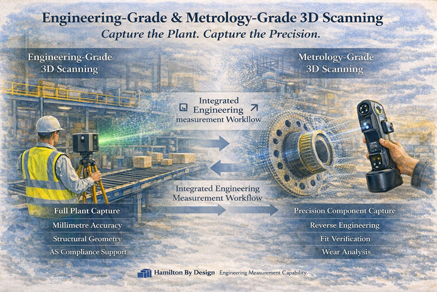
Supporting a Wide Range of CAD Data
Modern manufacturers rarely operate on a single CAD platform.
You may be working with:
- Native mechanical CAD files
- 3D assemblies
- 2D drawings
- STEP, IGES or neutral formats
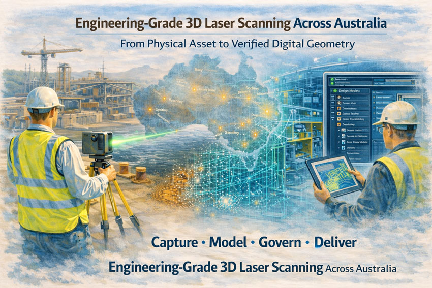
- Scan-to-CAD data
- Legacy models
- Supplier-generated geometry
Hamilton By Design supports a wide range of CAD data environments and helps bring them under structured governance.
We assist in:
- Managing multi-CAD environments
- Standardising revision structures across platforms
- Ensuring neutral formats are controlled
- Aligning scanned or reverse-engineered data with formal release processes
- Protecting geometry integrity across supply chains
Engineering governance must extend across all CAD formats — not just one system.
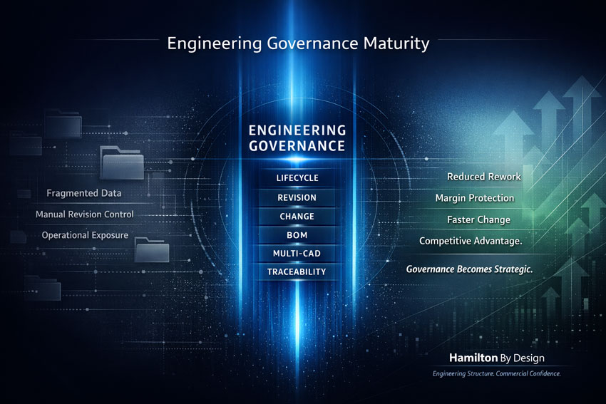
Leveling Up Engineering Governance
Many organisations are operating at a basic level of digital maturity.
Leveling up means:
- Moving from file storage to lifecycle control
- Moving from version confusion to structured revision discipline
- Moving from email approvals to controlled workflows
- Moving from reactive fixes to proactive governance
This is about increasing engineering maturity.
It is about embedding discipline into digital systems.
It is about reducing risk before it becomes rework.
Why the Combination Matters
When product structure control, drawing revision management, and multi-CAD governance are aligned:
- Bills of Materials reflect released revisions
- Engineering changes flow through structured pathways
- ERP and procurement operate from validated data
- Manufacturing builds from controlled documentation
- Management gains visibility and confidence
This is not just software implementation.
This is engineering governance embedded into your organisation.
The Australian Advantage
Australian manufacturers succeed through:
- Reliability
- Traceability
- Reduced rework
- Faster implementation of change
- Strong governance
- Protected intellectual property
Governance becomes a competitive advantage.
How Hamilton By Design Assists
We work with Australian manufacturers to:
- Review current engineering workflows
- Audit drawing and revision practices
- Implement structured governance frameworks
- Align engineering data with ERP and operations
- Integrate multiple CAD platforms under one disciplined structure
- Support digital uplift and maturity growth
We do not just provide engineering services.
We provide intellectual structure and digital discipline.

The Outcome
When engineering governance is elevated:
- Rework reduces
- Procurement errors decline
- Teams move faster
- Compliance strengthens
- Profit margins improve
If your organisation is still relying on shared drives and spreadsheets to manage engineering data, it may be time to level up.
Hamilton By Design — Engineering Governance for Competitive Advantage in Australian Manufacturing.