Engineering Design and Drafting Services | Hamilton By Design

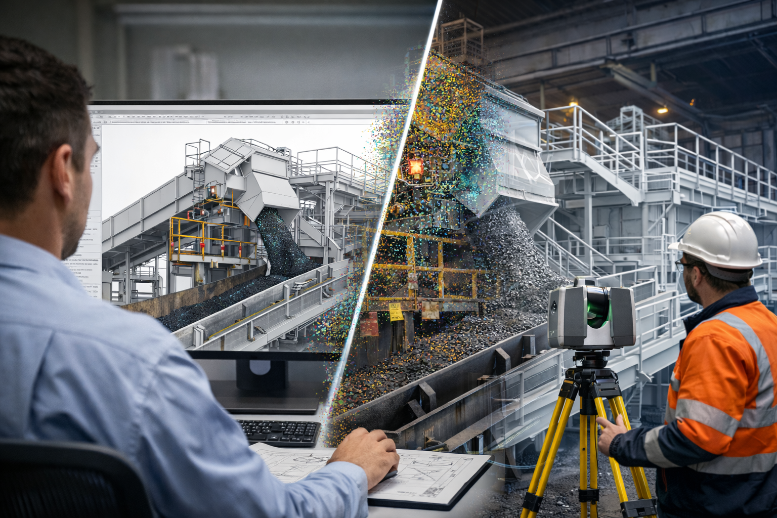
Engineering design and drafting for an industrial plant, showing 3D CAD modelling, technical drawings, LiDAR scanning and fabrication documentation.

Engineering Design and Drafting for Industrial, Mining and Infrastructure Projects

Successful engineering projects depend on more than a good idea. They require accurate information, practical design decisions and clear technical documentation that can be understood by engineers, fabricators, contractors, installers and asset owners.

Engineering design and drafting connect the initial project requirement with the final manufactured or installed result. They transform site information, calculations, concepts and operational requirements into coordinated 3D models and technical drawings.

Hamilton By Design provides Australian engineering design and drafting services for industrial plants, mining operations, manufacturing facilities, infrastructure projects and brownfield upgrades.

The objective is not simply to produce drawings. It is to create practical engineering information that supports decision-making, procurement, fabrication, construction, installation, operation and future maintenance.

What Is Engineering Design and Drafting?

Engineering design is the process of developing a practical solution to a technical problem. It considers how an asset should function, how it will be manufactured or constructed, how it interfaces with existing equipment and how it can be safely operated and maintained.

Engineering drafting communicates that solution through accurate models and drawings.

Depending on the project, engineering drafting deliverables may include:

  • three-dimensional CAD models
  • general arrangement drawings
  • manufacturing drawings
  • structural steel layouts
  • fabrication and workshop drawings
  • assembly and exploded views
  • pipework layouts and isometrics
  • equipment arrangement drawings
  • installation details
  • bills of materials
  • sections, elevations and details
  • as-built documentation
  • redline drawing updates

The design and drafting stages should work together. A technically sound concept must be converted into documentation that is clear, coordinated and suitable for its intended use.

Hamilton By Designโ€™s broader mechanical engineering services connect engineering analysis, site investigation, CAD modelling and drafting within a coordinated project workflow.

Why Engineering-Led Drafting Matters

Drafting software can create accurate lines and geometry, but software alone does not determine whether a design is practical.

Engineering-led drafting considers the real conditions that affect fabrication and installation, including:

  • available materials and standard sections
  • welding and machining requirements
  • practical tolerances
  • equipment loads
  • access for assembly and maintenance
  • lifting and installation constraints
  • clearances around existing plant
  • interfaces with structural, mechanical and civil systems
  • relevant Australian Standards
  • the sequence in which components will be manufactured and installed

A drawing may appear complete while still containing unresolved engineering issues. For example, a platform may fit within the available space but restrict maintenance access. A pipe route may avoid one structural member while conflicting with another service. A fabricated frame may be dimensionally correct but impossible to lift into position as a complete assembly.

Combining engineering knowledge with professional mechanical and structural drafting helps identify these issues before they reach the workshop or site.

Mechanical Design and Drafting

Mechanical design and drafting are used to develop machinery, plant equipment and supporting systems.

Typical applications include:

  • conveyors and transfer stations
  • chutes and hoppers
  • mechanical guards
  • pump and motor arrangements
  • tanks and process equipment
  • equipment support frames
  • pipework and ducting
  • lifting and handling equipment
  • maintenance platforms
  • replacement components
  • machine modifications
  • industrial equipment layouts

The process may begin with an existing concept, a site problem, a marked-up drawing, a physical component or a functional requirement.

A mechanical design can then be developed progressively through concept layouts, review models, detailed assemblies and fabrication drawings. This incremental approach allows assumptions to be checked and important interfaces to be confirmed before unnecessary detailing is completed.

Structural and Fabrication Drafting

Industrial projects frequently require new structural steel to support equipment, improve access or accommodate plant modifications.

Structural and fabrication drafting may include:

  • platforms and walkways
  • stairs, ladders and handrails
  • equipment support structures
  • conveyor support frames
  • maintenance access systems
  • structural modifications
  • connection details
  • base plates and brackets
  • lifting frames
  • workshop drawing packages

Fabrication drawings need to communicate more than overall dimensions. They may also need to identify materials, weld requirements, hole positions, fasteners, surface treatments, part numbers and assembly relationships.

Clear documentation reduces uncertainty in the workshop and allows questions to be addressed before fabrication begins.

Using 3D Laser Scanning to Improve Design Accuracy

Brownfield and retrofit projects often begin with incomplete or outdated information.

Original drawings may no longer represent the installed plant. Equipment may have been moved, structural steel modified, pipework rerouted or access systems added over many years.

Manual measurements can capture selected dimensions, but they may not provide enough information to understand a congested three-dimensional environment.

Engineering-grade 3D laser scanning captures millions of measured points across visible plant, equipment and structures. These points form a registered point cloud representing existing site conditions.

The point cloud can support:

  • existing-condition verification
  • equipment positioning
  • clash detection
  • access and clearance reviews
  • pipework routing
  • structural modification planning
  • installation sequencing
  • fabrication interface checks
  • as-built documentation
  • reverse engineering

Scanning is particularly valuable where site access is limited, shutdown periods are short or fabrication errors would be costly.

From Point Cloud to Engineering Model

A point cloud is a detailed spatial record, but it is not automatically an engineering model.

The dataset must be reviewed in relation to the project objective. Critical equipment, structures and interfaces can then be converted into practical CAD geometry.

Hamilton By Design provides point-cloud-to-AutoCAD services for projects requiring 2D plans, sections, elevations, layouts and engineering drawings developed from scanned site conditions.

Depending on the project, point-cloud information may be used to produce:

  • simplified equipment envelopes
  • structural steel models
  • mechanical assemblies
  • plant layouts
  • installation interfaces
  • existing pipework routes
  • general arrangement drawings
  • proposed-design overlays
  • fabrication geometry

Not every visible object needs to be modelled. The appropriate level of detail depends on how the information will be used.

Modelling only the important project interfaces can reduce processing time while preserving the information needed for engineering decisions.

SolidWorks Design and Drafting

Three-dimensional parametric modelling allows equipment, parts and assemblies to be developed in a coordinated digital environment.

Hamilton By Design uses SolidWorks for engineering and drafting to produce parts, assemblies, layouts, manufacturing drawings and design documentation.

A coordinated SolidWorks model can assist with:

  • visualising the proposed design
  • checking component relationships
  • identifying potential clashes
  • creating drawing views and sections
  • generating bills of materials
  • managing design revisions
  • developing sheet-metal components
  • producing assembly documentation
  • exporting neutral CAD formats for other project participants

Three-dimensional models also allow clients, fabricators and site teams to review a proposal before fabrication begins. This can make design discussions clearer than relying only on conventional two-dimensional drawings.

Engineering Design for Brownfield Projects

Brownfield projects involve modifying or adding to an existing facility.

They can be more complex than greenfield projects because the new design must fit around installed structures, operating equipment and established services.

Typical brownfield constraints include:

  • restricted installation space
  • unknown or undocumented geometry
  • limited site access
  • existing assets that must remain operational
  • short shutdown windows
  • multiple design interfaces
  • legacy equipment and drawings
  • restricted lifting and transport routes

A practical brownfield workflow may involve site inspection, laser scanning, point-cloud registration, CAD modelling, engineering review and staged drawing development.

The design team can first confirm the existing conditions and major interfaces. The proposed design can then be developed around reliable site data rather than assumptions.

Supporting Fabrication and Installation

Engineering design and drafting should make the next stage of the project easier.

Fabricators need clear information about what must be manufactured. Installers need to understand where components are located and how they connect to the existing plant. Project managers need confidence that interfaces have been reviewed.

Useful drawing packages may include:

  • drawing registers
  • general arrangement drawings
  • detailed part drawings
  • welded assembly drawings
  • installation layouts
  • material specifications
  • bills of materials
  • revision records
  • notes identifying site verification requirements

Where dimensions cannot be confirmed, assumptions and hold points should be clearly identified rather than hidden within the model.

This provides a more transparent basis for project decisions and helps prevent unverified information from being treated as confirmed site data.

Local and Australia-Wide Drafting Support

Hamilton By Design is based on the NSW Central Coast and supports projects throughout Australia.

Clients requiring local assistance can learn more about engineering drafting services on the Central Coast, including mechanical drafting, fabrication drawings, legacy drawing updates and as-built documentation.

Services can be provided for individual components, plant modifications, ongoing project support or larger engineering packages.

Frequently Asked Questions

What information is needed to begin an engineering drafting project?

Useful starting information may include sketches, photographs, existing drawings, dimensions, equipment data, design calculations, site constraints and the intended use of the final drawings. Where reliable site information is unavailable, a site inspection or 3D laser scan may be recommended.

Can drawings be produced from an existing physical component?

Yes. Existing components can be measured manually or captured using 3D scanning, depending on their size, complexity and required accuracy. The information can then be used to develop a reverse-engineered CAD model and manufacturing drawings.

What is the difference between a 3D model and a fabrication drawing?

A 3D model represents the geometry and relationships between components. A fabrication drawing communicates the dimensions, materials, tolerances, welds, finishes and other information required to manufacture the component. A model alone may not contain everything a fabricator needs.

Can old drawings be updated?

Yes. Legacy paper drawings, PDFs, marked-up prints and older CAD files can be reviewed and converted into updated digital drawings. Site verification may be required where the existing asset has been modified since the original drawings were issued.

Can point clouds be used directly for design?

Yes. Point clouds can be referenced in CAD software to measure existing conditions, position proposed equipment and check clearances. Selected geometry can also be converted into structured CAD models where required.

Do all objects in a scan need to be modelled?

No. The modelling scope should reflect the engineering objective. Modelling only the relevant equipment, structures and interfaces is often more efficient than creating a highly detailed model of the entire facility.

What drawing formats can be supplied?

Typical deliverables may include PDF, DWG and DXF drawings, together with SolidWorks, STEP, SAT or Parasolid models. Point-cloud formats may include E57, RCP, RCS and LAS, depending on the project requirements.

Can Hamilton By Design support both design and site capture?

Yes. Hamilton By Design combines site measurement, 3D LiDAR scanning, engineering design, CAD modelling and drafting. This creates a coordinated workflow from existing-condition capture through to engineering documentation.

Additional answers about scanning, modelling and engineering deliverables are available in the Hamilton By Design frequently asked questions.

Discuss Your Engineering Design and Drafting Project

Accurate engineering design and drafting create a reliable connection between an initial requirement and the final fabricated or installed asset.

By combining practical engineering experience, 3D CAD modelling, LiDAR scanning and clear technical documentation, Hamilton By Design helps clients reduce uncertainty, coordinate project interfaces and develop information that can be used confidently by fabricators, contractors and site teams.

Whether the requirement involves a single replacement component, a mechanical assembly, structural steel, a plant upgrade or a complete brownfield documentation package, the process should begin by defining the project objective, critical interfaces and required deliverables.

Hamilton By Design Co.
Mechanical Engineering | 3D Laser Scanning | 3D Modelling
Australia-wide engineering and project support


Hamilton By Design logo displayed on a blue tilted rectangle with a grey gradient background

Contact Us – Talk To Us

Name
Would you like us to arrange a phone consultation for you?
Address

Our clients:


Systems Engineering, Hazard Identification and Mining Safety

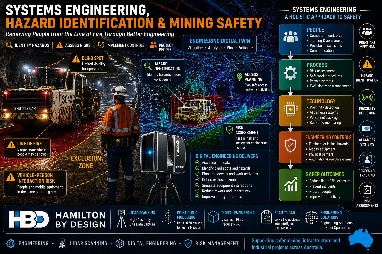
Systems engineering and mining safety infographic showing an underground shuttle car, exclusion zones, hazard identification, engineering digital twin, LiDAR scanning, risk assessment and engineering controls used to reduce line-of-fire risks and improve workplace safety in mining operations.

Lessons from a Preventable Underground Coal Mine Incident

The Technology Exists โ€“ So Why Are We Still Seeing These Incidents?

A recent Resources Safety & Health Queensland (RSHQ) investigation into a near-fatal underground coal mining incident has once again highlighted a challenge that continues to confront the mining industry.

The incident occurred at an underground coal mine near Emerald in Queensland’s Bowen Basin when a worker entered the blind spot of a shuttle car and was struck by the machine. Investigators identified several contributing factors including poor visibility, inadequate communication, high background noise, blind spots around mobile equipment and the absence of proximity detection technology. RSHQ described the event as entirely preventable and encouraged operators to consider technologies already being used successfully at other Queensland mines.

While incidents such as this are often discussed from an operational perspective, they also highlight a broader engineering challenge.

The real question is:

How do we design systems that prevent workers from being exposed to hazards in the first place?

This is where systems engineering becomes critically important.


What is Systems Engineering?

Systems engineering is the disciplined approach of understanding how people, equipment, processes, technology, procedures and the operating environment interact as a complete system.

Rather than focusing on individual components, systems engineering examines:

  • Human factors
  • Equipment design
  • Communication systems
  • Work procedures
  • Environmental conditions
  • Technology controls
  • Organisational culture
  • Training and competency
  • Risk management processes

When a serious incident occurs, it is rarely caused by a single failure.

Instead, multiple weaknesses align simultaneously.

In the Emerald incident, the shuttle car itself was not necessarily defective.

The system failed because:

  • Workers changed position without positive communication.
  • The vehicle operator was unaware of the workers’ location.
  • Visibility was limited.
  • Background noise masked movement.
  • No proximity detection technology was available.
  • Workers entered a line-of-fire zone.

A systems engineering approach asks:

What combination of controls could have prevented the event regardless of human error?


The Hierarchy of Controls

One of the most important principles in safety engineering is the Hierarchy of Controls.

Controls are generally ranked from most effective to least effective:

  1. Elimination
  2. Substitution
  3. Engineering Controls
  4. Administrative Controls
  5. Personal Protective Equipment

Many organisations rely heavily on procedures, training and pre-start discussions.

While these are important, they sit relatively low in the hierarchy.

Engineering controls are often more reliable because they do not depend entirely on human behaviour.

Examples include:

  • Proximity detection systems
  • AI camera systems
  • Collision avoidance systems
  • Personnel tracking systems
  • Physical barriers
  • Interlocks
  • Remote operation technology
  • Autonomous equipment

The objective should always be to engineer hazards out of the system wherever practical.


Hazard Identification Starts Before Work Begins

One of the most effective safety tools available is proactive hazard identification.

Many incidents occur because hazards are recognised only after work has commenced.

Hazard identification should occur during:

Project Planning

Before construction or maintenance work begins.

Design Reviews

Before equipment is fabricated or modified.

Shutdown Planning

Before personnel enter operational areas.

Pre-Start Meetings

Before workers commence each shift.

Field Risk Assessments

Immediately before performing a task.

A robust hazard identification process considers:

  • Mobile equipment interactions
  • Blind spots
  • Stored energy
  • Working at heights
  • Falling objects
  • Confined spaces
  • Vehicle movements
  • Emergency access
  • Simultaneous operations
  • Human factors

The goal is simple:

Identify hazards before they have an opportunity to cause harm.


Why Pre-Start Meetings Matter

In many operations, pre-start meetings can become routine.

Unfortunately, routine often leads to complacency.

The most effective pre-start meetings are not simply administrative exercises.

They provide an opportunity to discuss:

What Has Changed?

  • New equipment
  • New personnel
  • Different environmental conditions
  • Weather impacts
  • Operational changes

What Are Today’s Hazards?

  • Vehicle interactions
  • Exclusion zones
  • Ground conditions
  • Overhead hazards
  • Isolation requirements

What Are the Critical Controls?

  • Spotters
  • Communication methods
  • Isolation procedures
  • Permit requirements
  • Emergency response arrangements

What Could Go Wrong?

This question alone can significantly improve hazard awareness.

A quality pre-start discussion encourages workers to actively think about risk before entering the workplace.


Line-of-Fire Hazards Remain a Major Industry Risk

Across mining, construction, manufacturing and heavy industry, line-of-fire incidents continue to be one of the leading causes of serious injury and fatalities.

Line-of-fire hazards include situations where workers are exposed to:

  • Moving vehicles
  • Rotating equipment
  • Suspended loads
  • Stored energy
  • Pressurised systems
  • Falling objects
  • Uncontrolled equipment movement

Recent Queensland mining safety alerts have repeatedly highlighted similar themes:

  • Workers trapped between vehicles.
  • Workers entering exclusion zones.
  • Poor communication.
  • Lack of positive isolation.
  • Mobile equipment interactions.

The underlying hazards are often well understood.

The challenge is ensuring controls remain effective in real-world operating environments.


The Role of Digital Engineering and LiDAR Scanning

Modern engineering tools are creating new opportunities to identify and manage risk before work begins.

Engineering-grade LiDAR scanning and digital engineering workflows allow project teams to create accurate digital representations of operational facilities.

Applications include:

Access Planning

Identifying safe access routes.

Equipment Interaction Analysis

Assessing vehicle and personnel separation.

Shutdown Planning

Visualising work fronts before crews arrive onsite.

Clash Detection

Identifying conflicts before installation.

Exclusion Zone Development

Understanding hazardous interaction areas.

Emergency Planning

Reviewing evacuation routes and emergency access.

Hamilton By Design regularly supports projects through:

  • Engineering-grade LiDAR scanning
  • Point cloud modelling
  • Scan-to-CAD workflows
  • Digital engineering
  • Mechanical engineering
  • Brownfield modifications
  • As-built documentation

These tools provide project teams with accurate information that can improve both productivity and safety outcomes.


Proximity Detection Technology is Not New

One of the most significant observations from the recent incident is that proximity detection technology already exists.

In fact, underground mining industries have been investigating and deploying proximity detection systems around continuous miners and shuttle cars for many years. These systems can identify personnel entering predefined warning or hazard zones and initiate alarms, slowdowns or machine intervention depending on the system design.

Modern systems can provide:

  • Warning zones
  • Slow-down zones
  • Automatic stop functions
  • Personnel tracking
  • Vehicle interaction monitoring
  • AI-assisted hazard detection

The question is no longer whether the technology is available.

The question is how quickly and consistently industry adopts it.


Building Safer Systems

A mature safety culture understands that procedures alone are rarely enough.

The strongest organisations focus on building multiple layers of protection.

This includes:

People

  • Training
  • Competency
  • Communication

Processes

  • Risk assessments
  • Safe work procedures
  • Permit systems

Technology

  • Proximity detection
  • AI vision systems
  • Personnel tracking

Engineering

  • Equipment redesign
  • Physical barriers
  • Elimination of hazards

Leadership

  • Safety culture
  • Accountability
  • Continuous improvement

When these elements work together, the likelihood of serious incidents is dramatically reduced.


Final Thoughts

The recent underground coal mining incident serves as a powerful reminder that safety is fundamentally a systems engineering challenge.

The objective should not simply be to react to incidents.

The objective should be to design work environments where incidents are far less likely to occur.

Hazard identification, risk assessment, effective pre-start meetings, engineering controls and modern technologies all play a critical role in achieving this outcome.

As the mining industry continues to embrace digital engineering, LiDAR scanning, automation, AI systems and proximity detection technologies, there is a significant opportunity to remove people from the line of fire and create safer workplaces.

The technology exists.

The challenge is ensuring it is implemented before the next near miss becomes a fatality.


Hamilton By Design logo displayed on a blue tilted rectangle with a grey gradient background

References

  1. Resources Safety & Health Queensland (RSHQ) โ€“ Safety Alert: Underground shuttle car incident.
  2. Resources Safety & Health Queensland (RSHQ) โ€“ Vehicle interaction and line-of-fire safety alerts.
  3. Proximity Detection Systems in Underground Mines โ€“ Queensland Mining Industry Health and Safety Conference.
  4. Proximity Detection Options on Underground Mining Equipment.
  5. Safe to Work โ€“ Coal mine collision highlights parking procedure risks.

Contact Us – Talk to Us

Name
Would you like us to arrange a phone consultation for you?
Address
Australian Drafting logo featuring bold white text reading "Australian Drafting" centred on a blue rounded rectangle background.
Engineering Governance title graphic featuring bold white text reading "Engineering Governance" centred on a blue rounded rectangle background.
Mechanical, Structural & Pipework Drafting service banner by Hamilton By Design featuring white text on a blue background.
Mechanical engineering services
Blue rounded button with the text โ€œSolidWorks Designโ€ in white.
Finite Element Analysis (FEA) engineering simulation button
3D LiDAR Scanning Darwin for engineering surveys, laser scanning, reality capture and point cloud modelling services
3D LiDAR Scanning Australia engineering services for laser scanning, reality capture, scan-to-CAD, Scan-to-BIM and as-built documentation across Australia
3D LiDAR scanning services on the Central Coast providing engineering-grade laser scanning, point cloud capture, scan-to-CAD modelling and industrial reality capture for infrastructure and industrial projects.
3D LiDAR Scanning Perth for engineering surveys, laser scanning, reality capture and point cloud modelling services
3D LiDAR Scanning Sydney for engineering surveys, laser scanning, reality capture and point cloud modelling services
3D LiDAR Scanning Brisbane for engineering surveys, laser scanning, reality capture and point cloud modelling services
3D LiDAR Scanning Canberra for engineering surveys, laser scanning, reality capture and point cloud modelling services
3D LiDAR Scanning Newcastle for engineering surveys, laser scanning, reality capture and point cloud modelling services
3D LiDAR Scanning Adelaide for engineering surveys, laser scanning, reality capture and point cloud modelling services
https://www.hamiltonbydesign.com.au/scan-to-bim-services-australia-lidar-point-clouds-cad-modelling

Mechanical Engineering Muswellbrook NSW | Mining, CHPP & Industrial Engineering

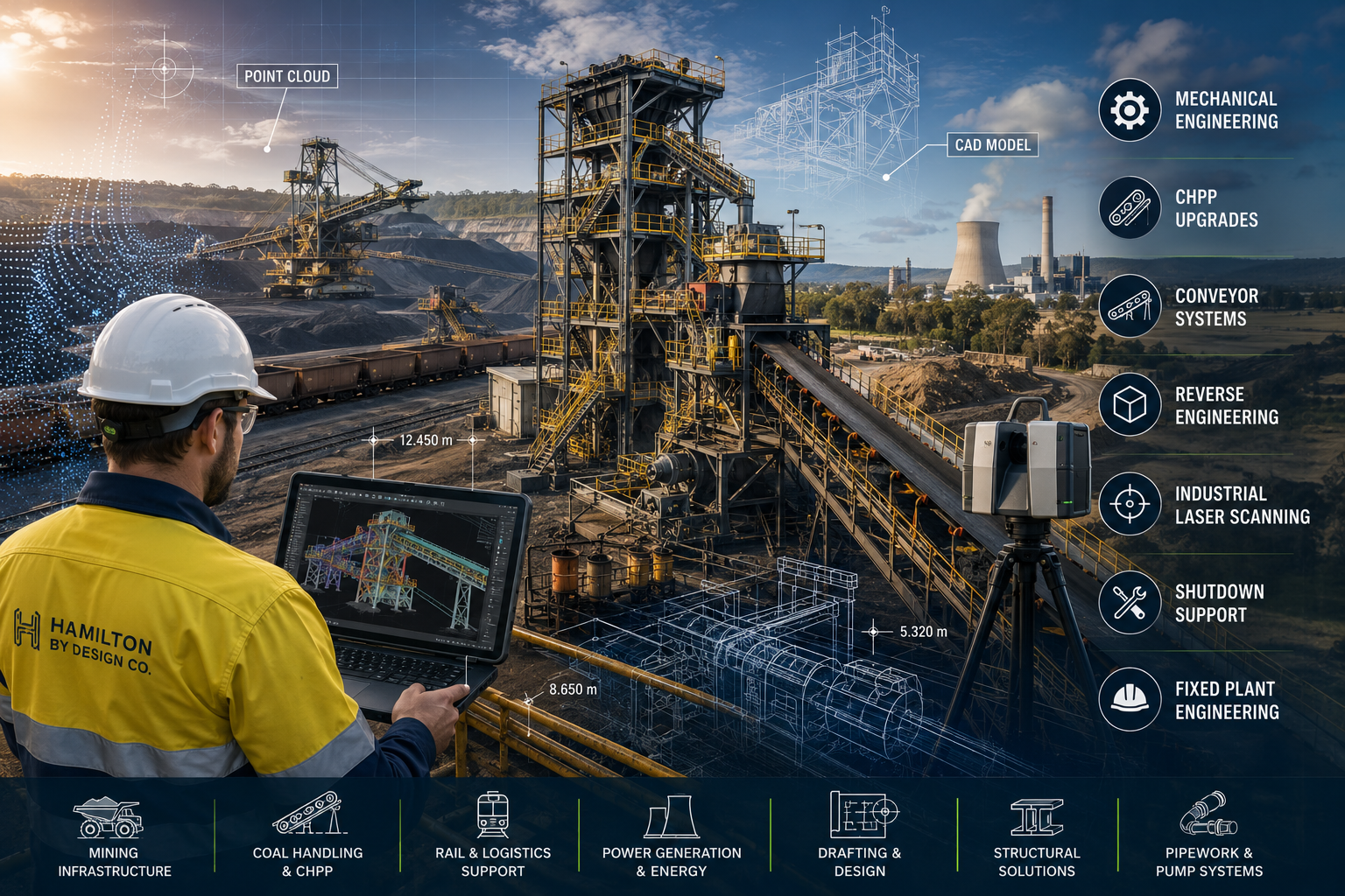
Mechanical engineering services in Muswellbrook NSW including CHPP upgrades, conveyor systems, industrial laser scanning, reverse engineering, fixed plant engineering and mining infrastructure design.

Mechanical Engineering Services in Muswellbrook NSW

Blue Gear and Spanner icon

Muswellbrook sits at the centre of one of Australia’s most important heavy industrial regions. Located in the Upper Hunter Valley, the area supports large-scale coal mining, Coal Handling and Preparation Plants (CHPP), power generation, rail infrastructure, bulk materials handling systems, maintenance workshops and emerging energy projects.

At Hamilton By Design Co., we provide engineer-led mechanical engineering, industrial laser scanning, reverse engineering and drafting services for mining, power generation and heavy industry throughout Muswellbrook and the wider Hunter Valley region.


Supporting Mining & Fixed Plant Infrastructure

The Muswellbrook region remains heavily connected to mining operations, bulk materials handling and fixed plant infrastructure. These facilities require ongoing engineering support for maintenance, shutdowns, brownfield upgrades and asset life extension programs.

Our team can assist with:

  • Conveyor system engineering
  • Transfer chute design
  • Crusher and screening plant upgrades
  • Pump station engineering
  • Structural steel modifications
  • Mechanical equipment installations
  • Walkways, platforms and access systems
  • Shutdown engineering support
  • Maintenance engineering documentation
  • Fabrication and workshop drawings
  • Asset integrity inspections

Many sites throughout the Hunter Valley operate ageing infrastructure that requires modification around existing operating plant. Accurate site measurement, engineering-grade scanning and practical engineering experience become critical when working in these environments.


3D LiDAR Scanning Hunter & Newcastle banner with white text on a blue background promoting engineering-grade laser scanning services for industrial, mining and infrastructure projects across the Hunter Valley and Newcastle region.
Mechanical Engineering Hunter & Newcastle banner promoting mechanical engineering services for mining, industrial plants, power generation, manufacturing and heavy industry throughout the Hunter Valley and Newcastle region.
Structural Drafting Hunter & Newcastle banner promoting structural drafting services for mining, industrial plants, power generation, manufacturing and infrastructure projects across the Hunter Valley and Newcastle region.

CHPP & Coal Handling Engineering

Coal Handling and Preparation Plants (CHPP) remain a major part of the Muswellbrook industrial landscape.

Hamilton By Design can support projects involving:

  • Conveyor transfers
  • Transfer tower upgrades
  • Coal sampling systems
  • Stacker and reclaimer infrastructure
  • Surge bins and hoppers
  • Dust suppression systems
  • Structural modifications
  • Pipework and pumping systems
  • Maintenance access upgrades
  • Shutdown planning and engineering

Our experience in bulk materials handling allows us to support both operational facilities and brownfield upgrade projects where existing site conditions present significant engineering challenges.


Power Generation & Energy Infrastructure

Muswellbrook has long been associated with major power generation assets including Bayswater Power Station and the former Liddell Power Station.

Mechanical engineering support remains essential across:

  • Turbine systems
  • Boiler infrastructure
  • Cooling water systems
  • Ash handling systems
  • Pipework upgrades
  • Structural inspections
  • Mechanical maintenance projects
  • Asset integrity assessments
  • Brownfield modifications
  • Renewable energy infrastructure

As the Hunter Valley continues transitioning toward energy storage and renewable infrastructure, engineering companies capable of supporting both legacy industrial assets and future energy projects will continue to play an important role.


3D LiDAR scanning and 3D modelling service button โ€” laser scanner capturing a point cloud for engineering and CAD modelling
Mechanical engineering services

Industrial 3D Laser Scanning in Muswellbrook

Hamilton By Design provides engineering-grade terrestrial LiDAR scanning services throughout Muswellbrook and the Hunter Valley.

Our scanning services support:

  • As-built verification
  • Conveyor systems
  • CHPP facilities
  • Power stations
  • Structural steelwork
  • Processing plants
  • Workshop facilities
  • Pipe racks
  • Tanks and vessels
  • Brownfield expansion projects

Deliverables can include:

  • Registered point clouds
  • E57 files
  • RCP and RCS datasets
  • CAD models
  • STEP files
  • SAT files
  • General Arrangement drawings
  • Fabrication drawings

Engineering-grade scanning reduces project risk by allowing accurate design work to occur around existing infrastructure before fabrication begins.


Reverse Engineering Services

Many mining and industrial sites throughout the Hunter Valley continue to operate equipment that is obsolete, difficult to source or no longer supported by the original manufacturer.

Hamilton By Design provides reverse engineering services for:

  • Mechanical components
  • Castings
  • Machined parts
  • Conveyor components
  • Wear liners
  • Pump assemblies
  • Couplings
  • Structural assemblies
  • Site-specific plant equipment

Using a combination of laser scanning, precision measurement, CAD modelling and practical manufacturing knowledge, we can recreate engineering models and fabrication drawings from existing components.


Mechanical Drafting & Design

Our drafting and design services support mining companies, fabrication workshops, contractors and maintenance teams throughout Muswellbrook and the Hunter Valley.

Services include:

  • Mechanical drafting
  • Structural drafting
  • Pipework drafting
  • Fabrication drawings
  • Workshop drawings
  • General Arrangement drawings
  • Site layouts
  • Conveyor detailing
  • Access platform design
  • Engineering documentation

We work across a range of deliverables including SolidWorks, AutoCAD, Inventor, STEP, DWG and PDF formats.


Supporting the Future of the Hunter Valley

The Upper Hunter region continues to undergo significant industrial transformation. While coal mining, bulk materials handling and fixed plant maintenance remain major industries, investment in energy storage, renewable energy and infrastructure upgrades is creating new engineering opportunities across the region.

Hamilton By Design supports clients throughout Muswellbrook, Singleton, Maitland, Newcastle and the wider Hunter Valley with engineer-led services focused on practical industrial outcomes.

Whether the project involves a conveyor upgrade, CHPP modification, power station infrastructure, reverse engineering, industrial laser scanning or mechanical drafting, our team can assist from site measurement through to detailed design documentation.

CHPP Engineering title graphic featuring bold white text reading "CHPP Engineering" centred on a blue rounded rectangle background.
Pipework Drafting title graphic featuring bold white text reading "Pipework Drafting" centred on a blue rounded rectangle background.
3D LiDAR Scanning for Engineering Projects title graphic featuring bold white text on a blue rounded rectangle background.

Contact Us – Talk to Us

Name
Would you like us to arrange a phone consultation for you?
Address

Our Clients:

3D CAD Modelling Australia service banner for Hamilton By Design
Finite Element Analysis (FEA) engineering simulation button
Structural drafting services button
Mechanical drafting services button
Australian Drafting logo featuring bold white text reading "Australian Drafting" centred on a blue rounded rectangle background.
Engineering Governance title graphic featuring bold white text reading "Engineering Governance" centred on a blue rounded rectangle background.
Engineering-Grade LiDAR Scanning title graphic featuring bold white text on a blue rounded rectangle background.
Mechanical engineering services
Australian Drafting logo featuring bold white text reading "Australian Drafting" centred on a blue rounded rectangle background.

Mechanical Engineering & 3D Scanning Somersby NSW | Hamilton By Design

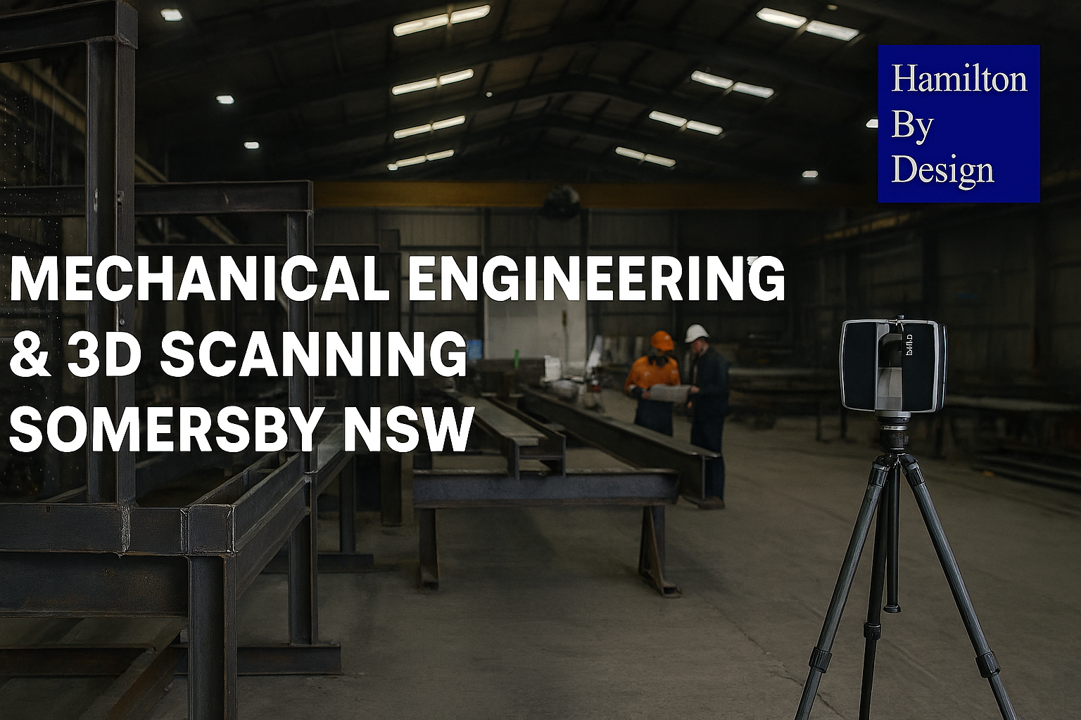
3D laser scanning and mechanical engineering Somersby NSW industrial site โ€“ Hamilton By Design

Engineering & Fabrication in Somersby

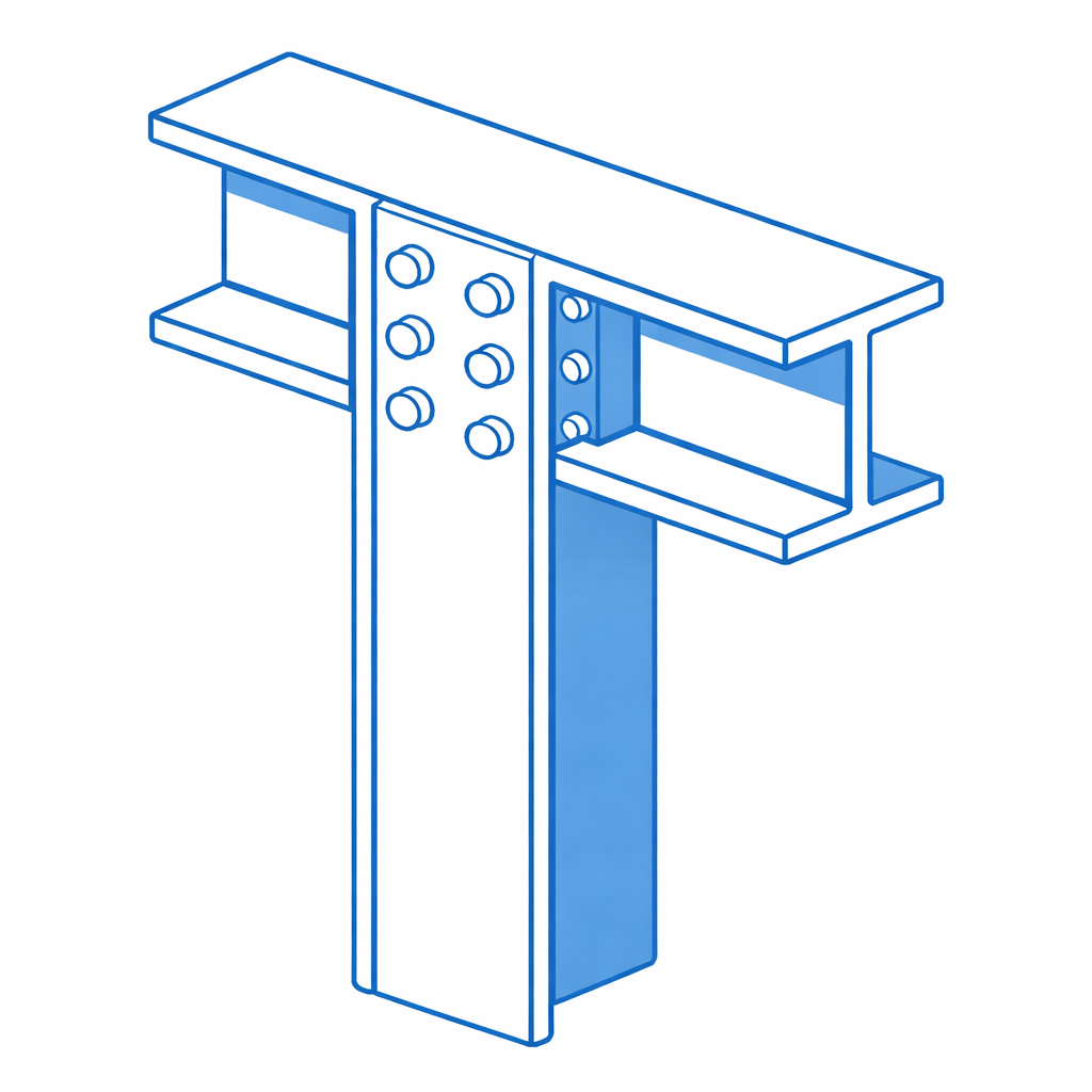
Structural steel I-beam bolted connection with column in isometric view.

Somersby is one of the Central Coastโ€™s most established industrial precincts, positioned directly off the M1 motorway between Gosford and Sydney. It is home to a strong network of steel fabricators, mechanical workshops, manufacturers, and industrial contractors, making it a key hub for construction, infrastructure, and plant-based projects.

From heavy fabrication yards to specialised engineering workshops, Somersby supports projects that require accuracy, coordination, and buildable design.

At Hamilton By Design, we work directly with businesses in Somersby to provide engineering-led 3D scanning, mechanical design, and fabrication-ready documentationโ€”ensuring projects fit first time and move efficiently from site to workshop.


Typical Companies in Somersby

The types of businesses youโ€™ll find in Somersby include:

Steel & Structural Fabricators

  • Structural steel workshops
  • Platform, walkway, and access system fabricators
  • Cladding and faรงade support steel manufacturers

Mechanical & Industrial Engineering Firms

  • Conveyor and materials handling specialists
  • Plant and machinery designers
  • Pump systems and processing equipment suppliers

Industrial Contractors & Builders

  • Mechanical installation contractors
  • Maintenance contractors for industrial plants
  • Construction firms delivering warehouses and infrastructure

Manufacturing & Processing Facilities

  • Food manufacturing plants
  • Packaging and production lines
  • Industrial processing facilities

These businesses rely heavily on accurate as-built data, engineering drawings, and coordination between site and fabrication.


How Hamilton By Design Supports Somersby Projects

3D Laser Scanning (LiDAR) โ€“ Site Capture

We capture existing conditions with high accuracy for:

  • Industrial plants and workshops
  • Structural steel and platforms
  • Pipework, conveyors, and mechanical systems
  • Brownfield and retrofit environments

Result:

  • Accurate point clouds ready for design
  • Reduced site rework and RFIs

Scan-to-CAD & As-Built Modelling

We convert site scans into usable engineering data:

  • 3D CAD models (SolidWorks)
  • 2D as-built drawings (plans, sections, elevations)
  • Layouts suitable for fabrication

Result:

  • Fabricators build from real geometry, not assumptions
  • Faster workshop turnaround

Mechanical Engineering & Design

Engineering-led support for:

  • Plant upgrades and modifications
  • Structural steel additions
  • Equipment installation and retrofits
  • Reverse engineering of existing components

Result:

  • Practical designs that match real site conditions
  • Reduced clashes during installation

Fabrication & Installation Support

We work closely with Somersby fabricators to deliver:

  • Fabrication drawings with tolerances
  • Weld details and assembly documentation
  • Fit-up strategies based on scan data

Result:

  • Components fit first time on site
  • Less rework, delays, and downtime

Typical Somersby Project Workflow

  1. Site scan at the Somersby facility or project site
  2. Point cloud processing and registration
  3. 3D modelling and engineering design
  4. Fabrication drawings issued
  5. Workshop fabrication by local fabricator
  6. Installation with minimal adjustment required

This workflow is critical in Somersby, where many projects involve existing structures, tight tolerances, and live industrial environments.


Why Engineering-Led Scanning Matters in Somersby

Somersby projects often involve brownfield conditions, where drawings are outdated or incomplete.

Traditional survey or basic scanning is not enough.

At Hamilton By Design:

  • The engineer is directly involved in the scan
  • Data is captured with fabrication in mind
  • Outputs are immediately usable for design and construction

This removes the gap between site, design, fabrication, and installation.


Local Advantage

Being active on the Central Coast, we understand:

  • Access and site constraints in Somersby
  • Working around active industrial operations
  • Coordination with local fabricators and contractors

This results in faster mobilisation, better communication, and ongoing project support.


Who We Work With in Somersby

  • Steel fabricators
  • Mechanical contractors
  • Industrial maintenance teams
  • Builders and project managers
  • Engineering consultants

Hamilton By Design logo displayed on a blue tilted rectangle with a grey gradient background

Work With Us in Somersby

If your project involves upgrading existing plant, fabricating new steelwork, or installing equipment into an existing structure, we provide accurate site data and engineering support to ensure it is delivered correctly the first time.

Contact Us – Talk to Us


Name
Would you like us to arrange a phone consultation for you?
Address

Our Clients

3D LiDAR scanning services on the Central Coast providing engineering-grade laser scanning, point cloud capture, scan-to-CAD modelling and industrial reality capture for infrastructure and industrial projects.
Drafting services on the Central Coast providing engineering drawings, fabrication detailing, as-built documentation, reverse engineering and CAD drafting for industrial and infrastructure projects.
Mechanical engineering services on the Central Coast providing industrial design, plant inspections, pump calculations, reverse engineering and engineering support for manufacturing, infrastructure and heavy industry projects.

Mechanical Engineering | Structural Engineering


Engineering Analysis & Simulation: Turning Engineering Assumptions into Measured Decisions

Engineering Analysis and Simulation infographic showing LiDAR scanning, scan-to-CAD workflows, finite element analysis (FEA), and digital engineering processes used to optimise industrial plant design and improve project outcomes.

In modern engineering projects, assumptions can quickly become expensive. Whether designing a transfer chute, assessing a structural support frame, modifying a conveyor system, or evaluating equipment performance, understanding how a system will behave before fabrication or installation can reduce risk, minimise rework, and improve project outcomes.

Engineering analysis and simulation allow engineers to move beyond simple calculations and create a deeper understanding of how equipment, structures, and systems will perform under real operating conditions.

At Hamilton By Design, we provide engineering analysis and simulation services to support mining, manufacturing, infrastructure, and industrial projects by combining engineering judgement with digital engineering tools and practical industry experience.

What is Engineering Analysis and Simulation?

Engineering analysis and simulation involve creating mathematical and digital representations of real-world systems to predict behaviour and performance before implementation.

Examples include:

  • Structural analysis
  • Finite Element Analysis (FEA)
  • Stress and deflection assessment
  • Equipment performance modelling
  • Load analysis
  • Materials handling analysis
  • Mechanical design validation
  • Existing asset assessments
  • Failure investigations
  • Brownfield modification studies

Rather than relying solely on assumptions or conservative estimates, simulation can provide measurable engineering data to support decision making.

Why Engineering Analysis Matters

Engineering projects often involve balancing multiple competing factors:

  • Safety
  • Cost
  • Performance
  • Weight
  • Reliability
  • Manufacturability
  • Maintenance access
  • Project schedule

Without engineering analysis, projects can encounter:

  • Unexpected structural failures
  • Excessive equipment wear
  • Over-designed systems
  • Fabrication clashes
  • Higher maintenance costs
  • Delays during installation

Simulation allows these issues to be identified earlier in the project lifecycle.

Hamilton By Design Engineering Analysis Services

Hamilton By Design offers engineering analysis and simulation services integrated with practical engineering workflows and reality capture technologies.

Our services can include:

Finite Element Analysis (FEA)

FEA can be used to assess:

  • Structural loading
  • Stress concentrations
  • Deflection
  • Equipment supports
  • Platform structures
  • Mechanical components
  • Existing assets

This allows engineers to identify areas of concern before fabrication or installation.

3D CAD Modelling Australia service banner for Hamilton By Design

Mechanical Design Validation

Engineering models can be assessed against:

  • Expected operational loads
  • Serviceability requirements
  • Design standards
  • Fatigue considerations
  • Practical operating conditions

Scan-to-Analysis Workflows

Traditional analysis often starts with assumptions about existing conditions.

Hamilton By Design can integrate:

  • Engineering-grade LiDAR scanning
  • Point cloud capture
  • Existing condition verification
  • Scan-to-CAD workflows

This allows simulations to be based on actual site geometry rather than estimated dimensions.

For brownfield mining and industrial projects this can significantly reduce uncertainty.

Applications Across Industry

Engineering analysis and simulation can support:

Mining

  • Conveyor systems
  • Transfer chutes
  • Processing equipment
  • Structural platforms
  • Plant modifications
  • Shutdown planning

Manufacturing

  • Production equipment
  • Structural supports
  • Machine layouts
  • Fabrication design

Infrastructure

  • Existing asset modifications
  • Structural assessments
  • Mechanical systems
  • Upgrade projects

Moving Beyond Assumptions

One of the biggest advantages of digital engineering is moving from:

Estimated geometry โ†’ Verified geometry

Rather than assuming dimensions from old drawings or field measurements, engineering analysis can be built around actual conditions captured through reality capture and CAD workflows.

This creates:

  • Improved confidence
  • Reduced project risk
  • Better fabrication outcomes
  • Reduced rework
  • More reliable project delivery
3D LiDAR scanning and 3D modelling service button โ€” laser scanner capturing a point cloud for engineering and CAD modelling
Mechanical engineering services

Supporting Better Engineering Decisions

At Hamilton By Design, engineering analysis is not treated as an isolated activity. It becomes part of a broader engineering workflow combining:

  • LiDAR scanning
  • Scan-to-CAD conversion
  • Mechanical design
  • Engineering documentation
  • Simulation and analysis
  • Project delivery support

The objective is not simply creating models. The objective is delivering engineering information that supports practical decisions and better outcomes.

Engineering analysis and simulation help projects move beyond assumptions and toward measurable, evidence-based engineering decisions.

Name
Would you like us to arrange a phone consultation for you?
Address

Our clients:

3D CAD Modelling Australia service banner for Hamilton By Design
Australian Drafting logo featuring bold white text reading "Australian Drafting" centred on a blue rounded rectangle background.
Engineering Governance title graphic featuring bold white text reading "Engineering Governance" centred on a blue rounded rectangle background.
Mechanical, Structural & Pipework Drafting service banner by Hamilton By Design featuring white text on a blue background.
Mechanical engineering services
Blue rounded button with the text โ€œSolidWorks Designโ€ in white.
Finite Element Analysis (FEA) engineering simulation button
3D LiDAR Scanning Darwin for engineering surveys, laser scanning, reality capture and point cloud modelling services
3D LiDAR Scanning Australia engineering services for laser scanning, reality capture, scan-to-CAD, Scan-to-BIM and as-built documentation across Australia
3D LiDAR scanning services on the Central Coast providing engineering-grade laser scanning, point cloud capture, scan-to-CAD modelling and industrial reality capture for infrastructure and industrial projects.
3D LiDAR Scanning Perth for engineering surveys, laser scanning, reality capture and point cloud modelling services
3D LiDAR Scanning Sydney for engineering surveys, laser scanning, reality capture and point cloud modelling services
3D LiDAR Scanning Brisbane for engineering surveys, laser scanning, reality capture and point cloud modelling services
3D LiDAR Scanning Canberra for engineering surveys, laser scanning, reality capture and point cloud modelling services
3D LiDAR Scanning Newcastle for engineering surveys, laser scanning, reality capture and point cloud modelling services
3D LiDAR Scanning Adelaide for engineering surveys, laser scanning, reality capture and point cloud modelling services

Chute Blockages and Build-Up in Mining Plants

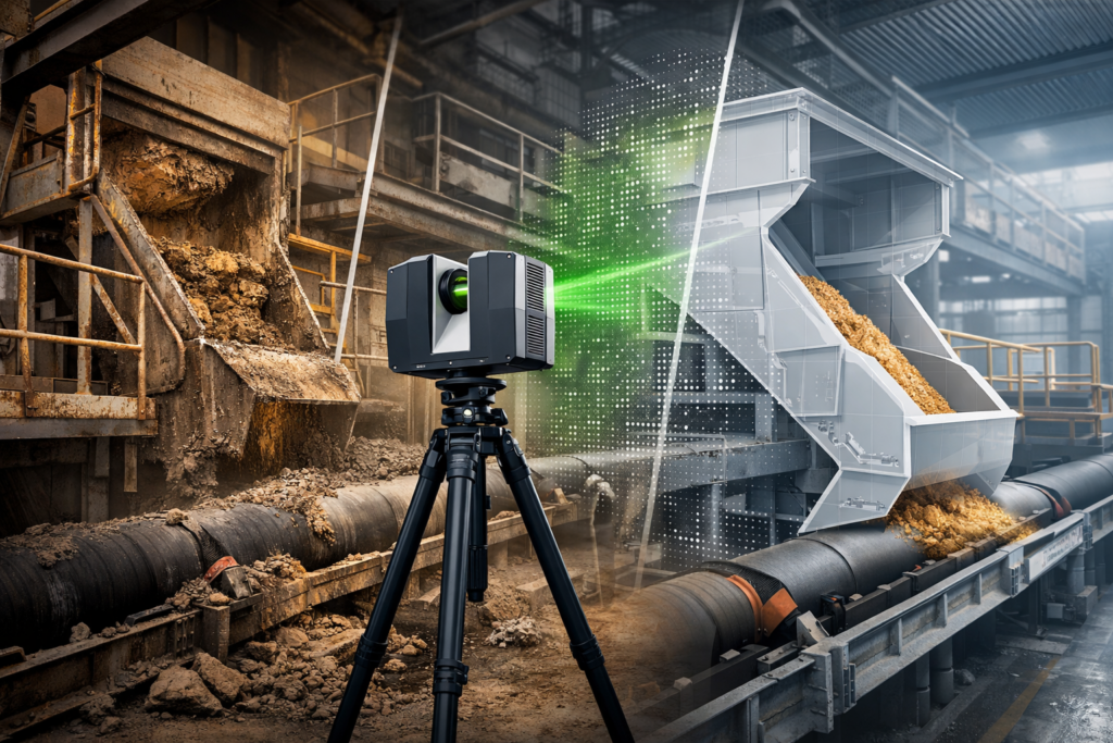
Point cloud mining infrastructure scanning connected to a 3D engineering model of a conveyor transfer chute.

Chute Blockages and Build-Up in Mining Plants | Hamilton By Design Co.

Transfer chute blockages and material build-up are some of the most common and costly problems in mining and bulk materials handling plants. A chute may look simple on paper, but in real operations it must control the flow of difficult materials under changing conditions, often within tight brownfield constraints.

When a chute begins to block, pack up, or accumulate build-up, the result is rarely limited to one small maintenance issue. Restricted flow can lead to reduced plant throughput, unplanned stoppages, excessive wear, spillage, dust, manual clean-outs, and increased shutdown risk.

At Hamilton By Design Co., we use engineering-grade 3D laser scanning, point cloud to CAD modelling, and practical mechanical design workflows to help clients understand why existing transfer chutes are failing and how those problems can be addressed with real-world upgrade solutions.

Why Transfer Chutes Block in Real Plants

A transfer chute does more than direct material from one conveyor to another. It must manage the velocity, direction, confinement, and discharge of a bulk solid that may behave very differently from day to day.

In theory, material should flow cleanly through the chute and load the receiving belt in a controlled manner. In practice, that often does not happen.

Blockages and build-up usually develop because of one or more of the following conditions:
  • Sticky or wet material
  • High fines content
  • Poor internal chute geometry
  • Dead zones or low-velocity regions
  • Sudden changes in direction
  • Inadequate clearances
  • Existing plant modifications not shown on old drawings
  • Wear plates or liners altering the internal flow path over time

This is one of the key lessons from bulk solids handling literature and modern transfer chute simulation work: a chute should be treated as a flow system, not just fabricated steelwork. If the bulk material is not guided correctly, the chute can quickly become the source of recurring reliability issues.
Common Signs of Chute Blockages and Build-Up

Many transfer chutes continue operating badly for months or years before a proper redesign is considered. The warning signs are often already there:

Frequent clean-outs

Operators or maintenance crews may need to manually remove compacted or hung-up material from inside the chute or around discharge points.

Reduced throughput

Partial restriction can reduce the chuteโ€™s effective flow area, limiting plant performance without always producing a full blockage.

Spillage and dust

As the internal flow path changes, material may discharge poorly, generating side loading, skirt leaks, and fugitive dust.

Uneven wear

Material build-up often redirects flow, concentrating abrasion and impact into localised wear zones.

Belt loading problems

A blocked or partially restricted chute can cause off-centre loading, surging, or unstable discharge onto the receiving conveyor.

Shutdown surprises

A chute that โ€œkind of worksโ€ during operation may become a major problem during shutdown replacement or upgrade works when its actual geometry and surrounding interfaces are finally exposed.

3D laser scanner capturing a blocked mining transfer chute with a digital redesign overlay above a conveyor.

Why Old Drawings Often Do Not Tell the Full Story

One of the most common issues in brownfield mining plants is that the existing chute does not match the drawings.

Over time, sites are modified. Liners are changed. Plates are added. Wear zones are patched. Access platforms are altered. Guards move. Structural members are added or cut back. Conveyor details are updated but not always captured in the plant model.

As a result, a design team can be asked to solve a blockage problem using information that is incomplete, outdated, or simply wrong.

This is where 3D laser scanning of the existing chute and surrounding plant becomes highly valuable. Instead of relying on assumptions, the project can begin with measured site reality.

How 3D Laser Scanning Helps Diagnose Chute Problems

3D laser scanning allows existing transfer stations, chute structures, conveyors, supports, platforms, and surrounding equipment to be captured accurately as an as-built point cloud.

This gives engineers and plant teams a much better starting point for understanding blockage and build-up issues.

With a high-quality site capture, it becomes easier to:

  • Verify the true chute geometry
  • Check whether the internal chute path matches legacy drawings
  • Measure clearances around the chute and conveyors
  • Identify brownfield constraints that will affect upgrades
  • Capture surrounding steelwork, guards, supports, access ways, and services
  • Build a reliable CAD base for redesign or shutdown planning
  • Reduce fit-up risk before fabrication

For blocked or restricted transfer points, this matters because the problem is rarely isolated to one plate or one wear liner. The full transfer arrangement often needs to be understood in context.

Point Cloud to CAD for Chute Upgrade Projects

Once the existing chute and surrounding transfer area have been scanned, the point cloud can be converted into useful engineering models and drawing outputs.

Depending on project requirements, this may include:

  • Existing arrangement models
  • AutoCAD model space layouts
  • General arrangement drawings
  • Section views through critical transfer zones
  • Conveyor interface checks
  • Structural and access reference models
  • Base geometry for redesign concepts

This step is important because scanning alone does not solve the problem. The value comes from turning measured site conditions into a workable engineering model that supports analysis, redesign, communication, and project delivery.

Typical Causes of Chute Build-Up

No two plants are identical, but the same broad patterns appear again and again in mining and bulk materials handling systems.

Poor chute geometry

Flat ledges, abrupt transitions, internal obstructions, and shallow flow surfaces can create low-energy zones where material begins to hang up.

Material variability

A chute may perform reasonably with dry product but fail badly when moisture, fines content, or feed consistency changes.

Wear changing the flow path

As liners wear, the material trajectory and internal contact pattern can change. In some cases, past repairs can unintentionally make the problem worse.

Inadequate discharge control

If the material is not being guided cleanly through the chute, unstable flow can create recirculation, impact concentration, and inconsistent discharge onto the receiving belt.

Brownfield constraints

Legacy chute geometry is often shaped by what could fit at the time, not by what offered the best flow. This is especially true where upgrades have been added over many years.

A Practical Engineering Approach

At Hamilton By Design Co., we see chute blockage problems as both a materials handling issue and a brownfield engineering issue.

That means the practical workflow is often:

1. Capture the existing transfer area

We scan the chute, conveyors, structure, and surrounding plant to create an accurate as-built record.

2. Build the engineering base model

We convert the point cloud into usable CAD references for design, review, and planning.

3. Understand the real constraint

We assess what the current chute is doing, what clearances exist, and where the upgrade risks are likely to sit.

4. Support redesign and upgrade works

The as-built data can then be used to support mechanical design, chute modification concepts, shutdown planning, and fabrication fit-up.

This practical approach is especially useful where the site is already experiencing recurring clean-outs, ongoing maintenance cost, or uncertainty around existing geometry.

Where This Applies

This type of work is relevant across a wide range of bulk materials handling environments, including:

  • Coal handling plants
  • Hard rock mining operations
  • Quarry transfer systems
  • Materials handling conveyors
  • Process plant transfer stations
  • Brownfield chute replacement projects

Why This Matters

Transfer chutes are often underestimated. A poorly performing chute can quietly create lost production, repeated maintenance, high cleanup cost, and shutdown complications for years.

The real lesson from bulk solids handling practice is that a chute should not be designed or upgraded as just a fabricated box. It must be understood as part of a controlled material flow system, operating within the real physical constraints of the plant.

When those constraints are not fully understood, blockage and build-up problems tend to repeat.

That is why 3D laser scanning, point cloud to CAD modelling, and measured as-built engineering data are such valuable first steps in solving restricted or unreliable transfer points.

3D LiDAR scanning and 3D modelling service button โ€” laser scanner capturing a point cloud for engineering and CAD modelling
Mechanical engineering services

Need Support with an Existing Chute Problem?

If your site is dealing with chute blockages, material build-up, inaccurate plant drawings, or shutdown upgrade risk, Hamilton By Design Co. can help capture the existing conditions and provide an engineering-ready base for the next stage of the project.

Hamilton By Design logo displayed on a blue tilted rectangle with a grey gradient background

We support mining and industrial clients with:

  • 3D laser scanning of existing plant
  • Point cloud to CAD conversion
  • Existing condition modelling
  • Brownfield upgrade support
  • Chute and transfer station design workflows

Contact Hamilton By Design Co. to discuss your existing chute, transfer point, or scanning requirement.

Name
Would you like us to arrange a phone consultation for you?
Address

Our clients

CHPP Engineering title graphic featuring bold white text reading "CHPP Engineering" centred on a blue rounded rectangle background.
Pipework Drafting title graphic featuring bold white text reading "Pipework Drafting" centred on a blue rounded rectangle background.
3D LiDAR Scanning for Engineering Projects title graphic featuring bold white text on a blue rounded rectangle background.
3D CAD Modelling Australia service banner for Hamilton By Design