Tomago + Mechanical Engineering + 3D Laser Scanning + Industrial Design Services = Hamilton By Design
Supporting Tomago’s Manufacturing, Aluminium & Industrial Infrastructure Sector
Tomago is one of the Hunter Region’s most significant industrial and manufacturing centres. Located between Newcastle, the Hunter Valley and Port Stephens, the region is home to major industrial facilities, manufacturing operations, mining support services and one of Australia’s largest aluminium smelters.
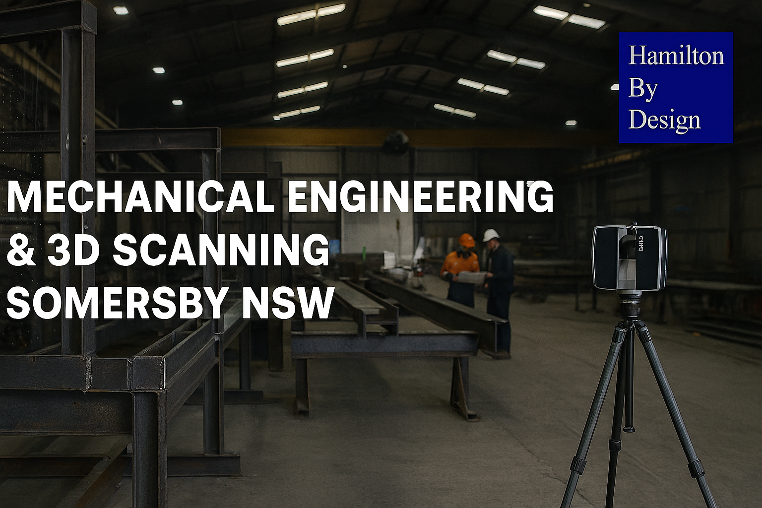
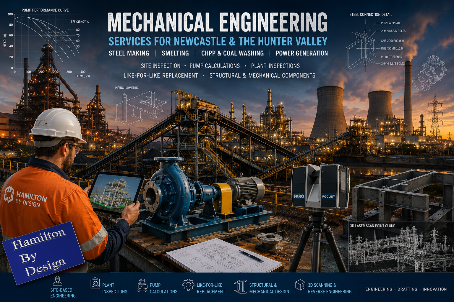
At Hamilton By Design, we provide engineering-grade 3D laser scanning, mechanical engineering, drafting, reverse engineering and industrial asset capture services throughout Tomago and the greater Newcastle region.
Our team supports industrial facilities requiring accurate site data, practical engineering solutions and detailed design support for brownfield upgrades, manufacturing projects, maintenance works and industrial infrastructure development.


Why Tomago?
Tomago is strategically positioned within one of Australia’s most productive industrial corridors.
The area supports:
- Aluminium production
- Heavy manufacturing
- Industrial fabrication
- Mining support services
- Conveyor manufacturing
- Materials handling systems
- Mechanical workshops
- Structural steel fabrication
- Industrial warehousing
- Defence-related manufacturing
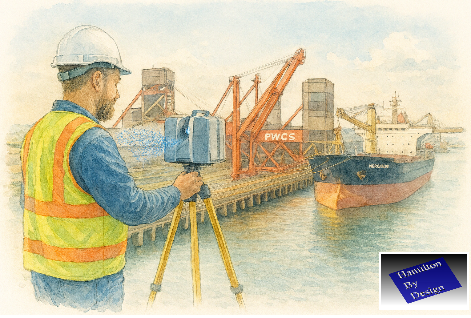
Its proximity to Newcastle Port, Newcastle Airport, the Hunter Valley mining region and major freight routes makes Tomago a critical industrial hub supporting projects across New South Wales and Australia.
Engineering-Grade 3D Laser Scanning
Not all scans are equal.
At Hamilton By Design, we specialise in engineering-grade terrestrial LiDAR scanning designed to support real engineering outcomes.
Our scanning services assist with:
- Aluminium smelter upgrades
- Manufacturing facilities
- Conveyor systems
- Pipework installations
- Structural steel modifications
- Brownfield plant upgrades
- Shutdown planning
- Equipment replacement projects
- As-built verification
- Industrial asset capture
We deliver registered point cloud data suitable for:
- SolidWorks
- Autodesk Revit
- Navisworks
- AutoCAD
- Inventor
- Recap
- Industrial plant design platforms
Whether your project requires a single processing area scanned or a complete industrial facility digitally captured, our team can provide practical engineering-grade data for design and construction purposes.
Supporting Aluminium Smelting Infrastructure
Tomago is internationally recognised for aluminium production.
Large industrial facilities operating within the region require ongoing engineering support for:
- Materials handling systems
- Potline infrastructure
- Conveyor systems
- Access platforms
- Structural steel modifications
- Pipework systems
- Mechanical equipment upgrades
- Maintenance and shutdown projects
Hamilton By Design provides engineering support services that assist industrial facilities with accurate site information and practical design outcomes.
Mechanical Engineering & Industrial Design
Industrial facilities evolve continuously.
Equipment changes, production requirements increase and ageing infrastructure often requires modification or replacement.
Our services include:
Mechanical Engineering
- Materials handling systems
- Conveyor systems
- Chutes and transfer points
- Rotating equipment
- Pump systems
- Industrial plant upgrades
- Maintenance engineering
Structural Design Support
- Access platforms
- Stairs and handrails
- Equipment supports
- Pipe racks
- Maintenance structures
- Walkways and industrial access systems
Reverse Engineering
Many industrial facilities continue to operate legacy equipment where original drawings are no longer available.
Our reverse engineering services support:
- Castings
- Machined components
- Pump equipment
- Wear components
- Conveyor assemblies
- Obsolete spare parts
- Industrial machinery
Supporting Mining & Materials Handling Industries
Tomago is closely connected to the Hunter Valley mining industry.
Many local businesses manufacture, repair and support equipment used within:
- Coal preparation plants (CHPP)
- Conveyor systems
- Bulk materials handling facilities
- Rail infrastructure
- Export terminals
- Mining operations
Hamilton By Design provides engineering support for both new and existing industrial infrastructure.
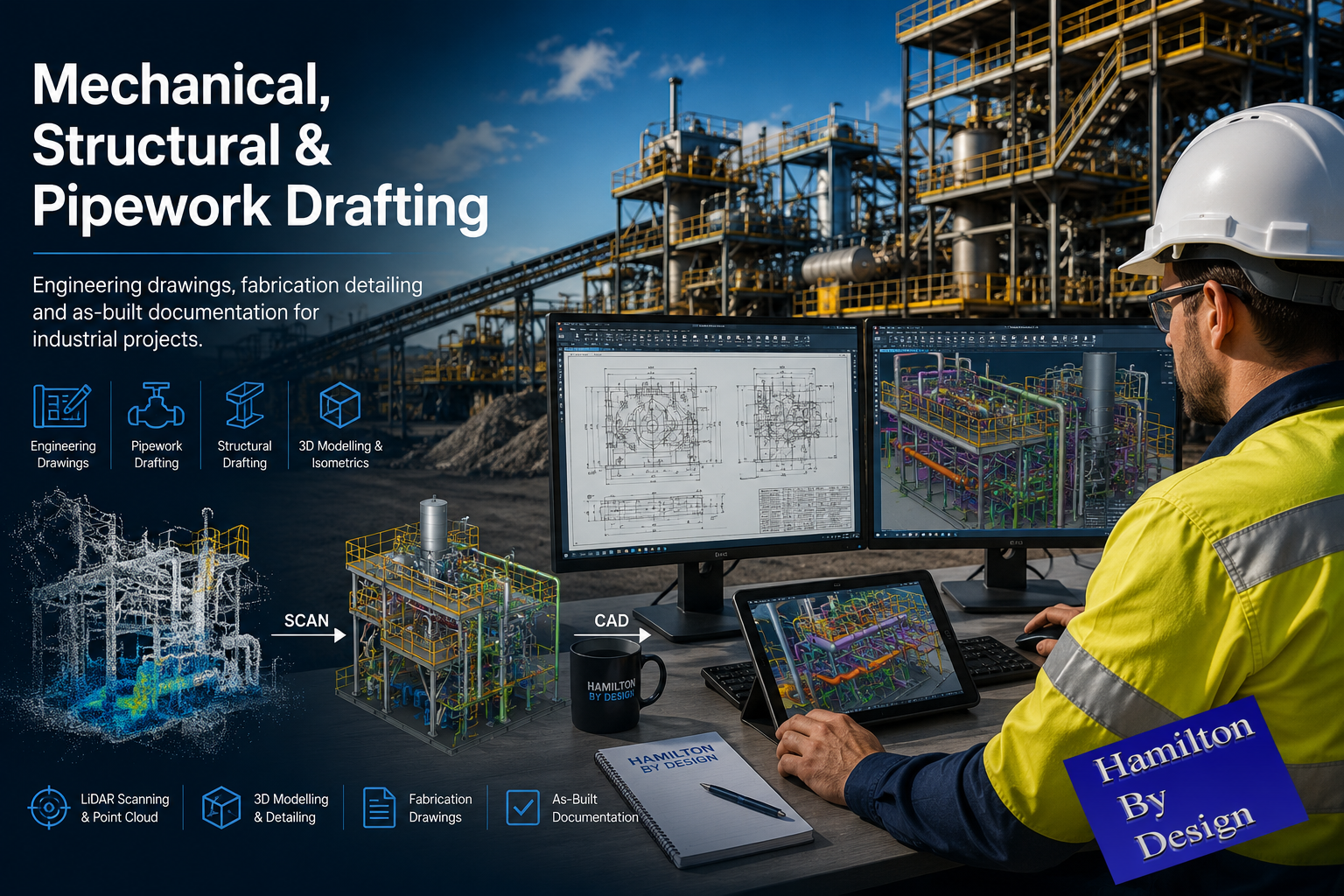
Industrial Asset Capture & Scan to CAD
Accurate site information reduces project risk.
Our asset capture services provide:
- Registered point clouds
- 3D models
- Scan to CAD conversion
- Existing condition documentation
- Equipment verification
- Clash detection
- Digital engineering workflows
These services assist contractors, manufacturers, engineers and project teams when working within active industrial facilities.
Why Hamilton By Design?
Hamilton By Design combines practical trade experience with engineering capability.
Our background includes:
- Mechanical engineering
- Fitting and machining
- Industrial drafting
- Manufacturing support
- Mining operations
- Smelting facilities
- Industrial maintenance
- Site-based engineering
We understand that engineering solutions must be practical, manufacturable and suitable for installation within real operating environments.
Servicing Tomago & the Hunter Region
Hamilton By Design supports projects throughout:
- Tomago
- Hexham
- Beresfield
- Thornton
- Mayfield West
- Steel River Industrial Estate
- Kooragang Island
- Newcastle
- Maitland
- Rutherford
- Singleton
- Muswellbrook
- The Hunter Valley
Whether you require engineering-grade laser scanning, mechanical drafting, reverse engineering support or industrial design services, our team is available to assist.
Engineering Support for Tomago Industry
Hamilton By Design provides engineering-grade 3D laser scanning, mechanical engineering, drafting and industrial asset capture services supporting manufacturing, aluminium production, mining infrastructure and industrial facilities throughout Tomago and the Hunter Region.
Talk to Us – Contact Us
Contact our team to discuss your next industrial project and discover how accurate site data and practical engineering experience can improve project delivery, reduce risk and support long-term asset performance.


Our Clients: