In today’s world, accuracy and efficiency can make or break a project. Whether you’re working in architecture, construction, engineering, or product design, you need reliable data — and you need it fast. That’s where 3D point clouds come in.
But there’s an important catch: not all scans are created equal. The difference between an average scan and a great one often comes down to the person behind the scanner. Having someone who understands 3D modeling take the scans can dramatically improve your project’s accuracy, reliability, and overall success.
Let’s break down why.
The Power of 3D Point Clouds
Point clouds are essentially millions of tiny data points that capture the shape of an object, room, or entire site. Together, they create a highly detailed digital snapshot of the real world.
Here’s why this matters:
Precision you can trust – Point clouds deliver incredibly detailed measurements, capturing even the smallest curves and angles.
Nothing gets missed – Multiple scan angles ensure a full, 360° view of your site or object.
Speed and efficiency – What used to take hours (or days) with manual measurements can be captured in minutes.
Built-in context – You’re not just getting numbers; you’re getting a complete digital environment to work inside.
Future-proof data – Once you have a scan, you have a permanent record of your space, ready to use months or years later.
From clash detection to as-built verification, point clouds save time, reduce errors, and make collaboration across teams smoother than ever.
Why the Person Taking the Scan Matters
While technology is powerful, experience is what makes the results reliable. Having a skilled 3D modeler operate the scanner can be the difference between a good project and a great one.
Here’s why an expert makes all the difference:
They know what matters – A modeler understands which details are critical for your project and ensures they’re captured.
Fewer gaps, fewer surprises – Experienced pros know how to plan scan positions to cover every angle and avoid blind spots.
Cleaner, more accurate data – They reduce common issues like noise, misalignment, or missing sections that can throw off your model.
Time saved, headaches avoided – No one wants to redo a scan halfway through a project. A professional ensures you get it right the first time.
Confidence from start to finish – When you know your model is accurate, you can move forward with design and construction decisions without second-guessing.
In short: a great scanner operator doesn’t just deliver data — they deliver peace of mind.
The Bottom Line
3D point clouds are already transforming how projects are planned and delivered. But pairing them with an experienced 3D modeler takes things to the next level.
You’ll get better data, faster turnarounds, and a far lower risk of costly mistakes. And when your goal is to deliver projects on time, on budget, and with zero surprises, that’s an edge you can’t afford to miss.
Getting Coal, Hard Rock, and ROM Material Flow Right
Chute design is one of the most critical yet challenging aspects of mining and mineral processing. Whether you are handling coal, hard rock ore, or raw ROM material, chutes and transfer stations are the unsung workhorses of every operation. When designed well, they guide material smoothly, minimise wear, and keep conveyors running. When designed poorly, they cause blockages, spillage, excessive dust, and expensive downtime.
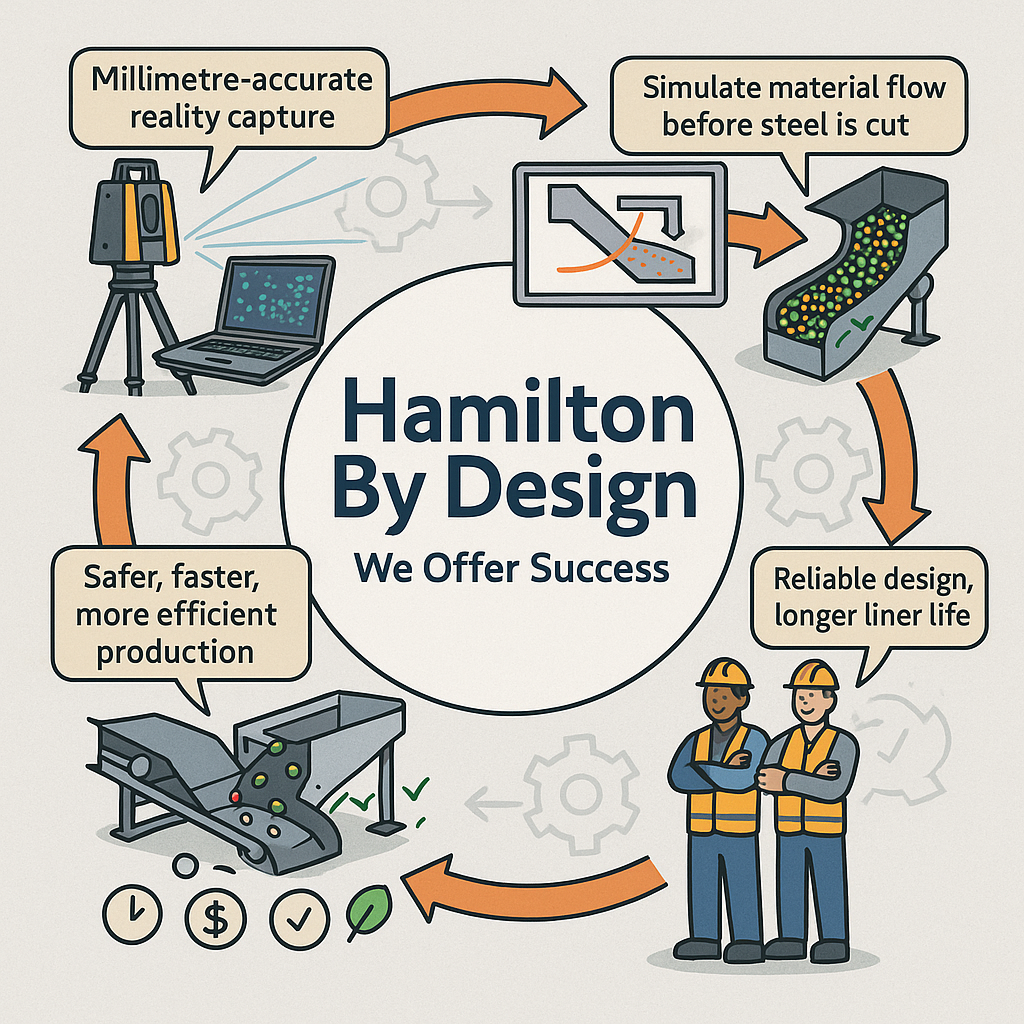
Modern chute design has moved far beyond rules of thumb and back-of-the-envelope sketches. Today, successful projects rely on accurate as-built data, particle trajectory analysis, and advanced Discrete Element Method (DEM) simulation to predict, visualise, and optimise material flow before steel is cut. In this article, we explore why these tools have become essential, how they work together, and where software can — and cannot — replace engineering judgement.
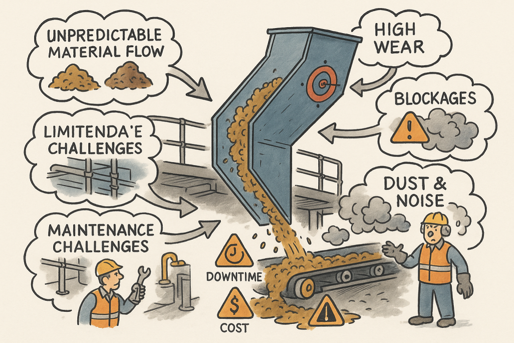
The Challenge of Chute Design
Coal and hard rock have very different flow behaviours. Coal tends to be softer, generate more dust, and be prone to degradation, while hard rock is more abrasive and can damage chutes if impact angles are not controlled. ROM material adds another level of complexity — oversize lumps, fines, and moisture variation can cause hang-ups or uneven flow.
Chute design must balance several competing objectives:
Control the trajectory of incoming material to reduce impact and wear
Prevent blockages by maintaining flowability, even with wet or sticky ore
Manage dust and noise to meet environmental and workplace health requirements
Fit within existing plant space with minimal modification to conveyors and structures
Be maintainable — liners must be accessible and replaceable without excessive downtime
Meeting all these goals without accurate data and simulation is like trying to design in the dark.
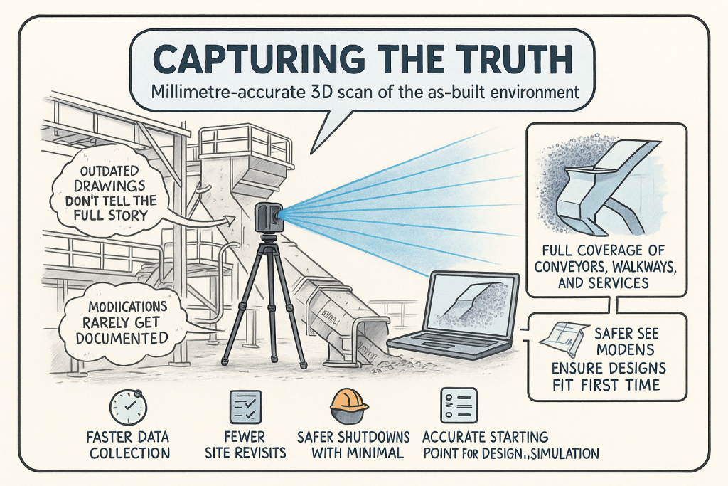
Capturing the Truth with 3D Scanning
The first step in any successful chute project is to understand the as-built environment. In many operations, drawings are outdated, modifications have been made over the years, and the real plant geometry may differ from what is on paper. Manual measurement is slow, risky, and often incomplete.
This is where 3D laser scanning changes the game. Using tripod-mounted or mobile LiDAR scanners, engineers can capture the entire transfer station, conveyors, surrounding steelwork, and services in a matter of hours. The result is a dense point cloud with millimetre accuracy that reflects the true state of the plant.
From here, the point cloud is cleaned and converted into a 3D model. This ensures the new chute design will not clash with existing structures, and that all clearances are known. It also allows maintenance teams to plan safe access for liner change-outs and other work, as the scanned model can be navigated virtually to check reach and access envelopes.
Understanding Particle Trajectory
Once the physical environment is known, the next challenge is to understand the particle trajectory — the path that material takes as it leaves the head pulley or previous transfer point.
Trajectory depends on belt speed, material characteristics, and discharge angle. For coal, fine particles may spread wider than the coarse fraction, while for ROM ore, large lumps may follow a ballistic path that needs to be controlled to prevent impact damage.
Accurately modelling trajectory ensures that the material enters the chute in the right location and direction. This minimises impact forces, reducing wear on liners and avoiding the “splash” that creates spillage and dust. It also prevents the material from hitting obstructions or dead zones that could lead to build-up and blockages.
Modern software can plot the trajectory curve for different loading conditions, providing a starting point for chute geometry. This is a critical step — if the trajectory is wrong, the chute design will be fighting against the natural path of the material.
The Power of DEM Simulation
While trajectory gives a first approximation, real-world flow is far more complex. This is where Discrete Element Method (DEM) simulation comes into play. DEM models represent bulk material as thousands (or millions) of individual particles, each following the laws of motion and interacting with one another.
When a DEM simulation is run on a chute design:
You can visualise material flow in 3D, watching how particles accelerate, collide, and settle
Impact zones become clear, showing where liners will wear fastest
Areas of turbulence, dust generation, or segregation are identified
Build-up points and potential blockages are predicted
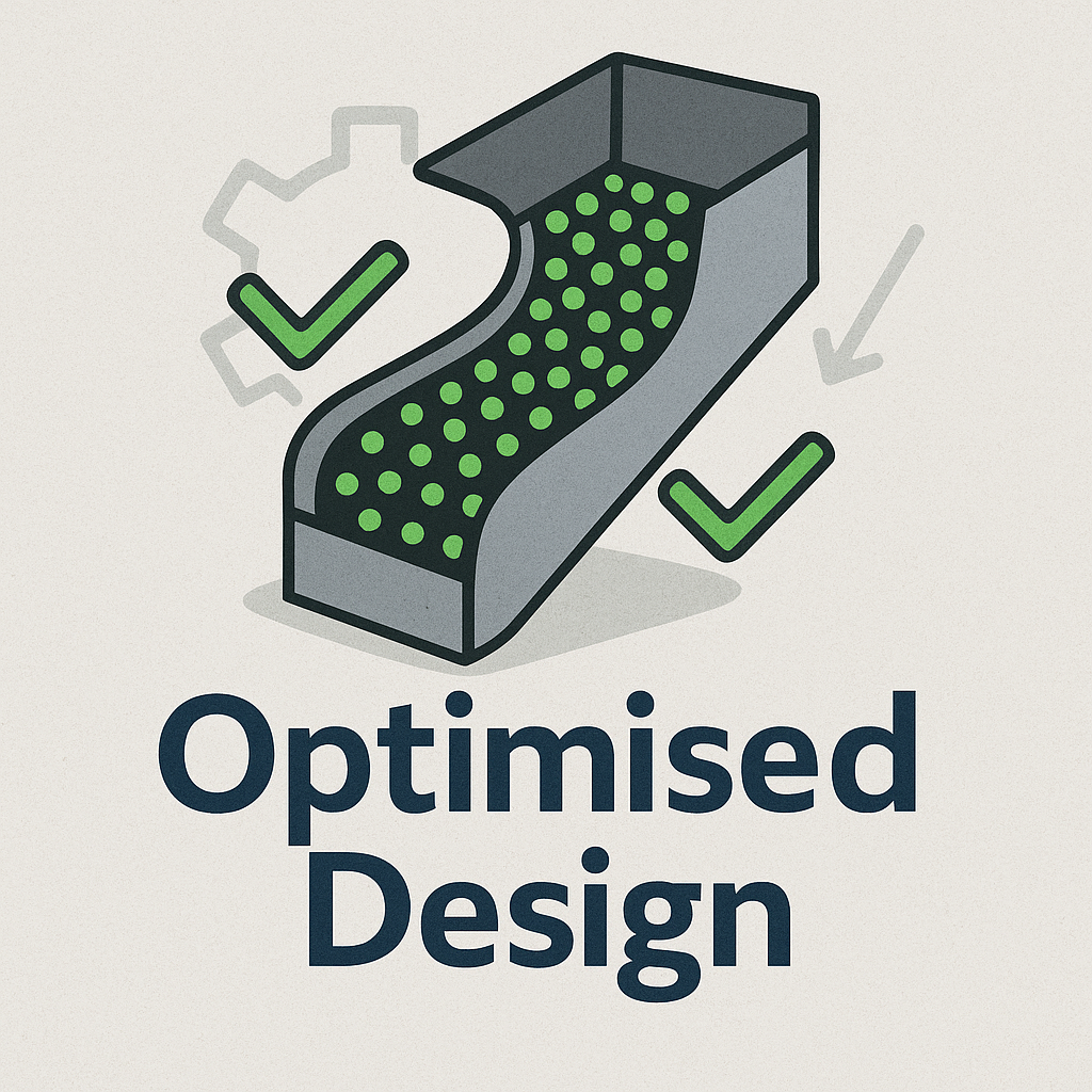
This allows engineers to experiment with chute geometry before fabrication. Angles can be changed, ledges removed, and flow-aiding features like hood and spoon profiles or rock-boxes optimised to achieve smooth, controlled flow.
For coal, DEM can help ensure material lands gently on the receiving belt, reducing degradation and dust. For hard rock, it can ensure that the energy of impact is directed onto replaceable wear liners rather than structural plate. For ROM ore, it can help prevent oversize lumps from wedging in critical locations.
🖥 Strengths and Limitations of Software
Modern DEM packages are powerful, but they are not magic. Software such as EDEM, Rocky DEM, or Altair’s tools can simulate a wide range of materials and geometries, but they rely on good input data and skilled interpretation.
Key strengths include:
Ability to model complex, 3D geometries and particle interactions
High visualisation power for communicating designs to stakeholders
Capability to run multiple scenarios (different feed rates, moisture contents, ore types) quickly
However, there are limitations:
Material calibration is critical. If the particle shape, friction, and cohesion parameters are wrong, the results will not match reality.
Computational cost can be high — detailed simulations of large chutes with millions of particles may take hours or days to run.
Engineering judgement is still needed. Software will not tell you the “best” design — it will only show how a proposed design behaves under given conditions.
That’s why DEM is best used as part of a holistic workflow that includes field data, trajectory analysis, and experienced design review.
From Model to Real-World Results
When the simulation results are validated and optimised, the design can be finalised. The point cloud model ensures the chute will fit in the available space, and the DEM results give confidence that it will perform as intended.
This means fabrication can proceed with fewer changes and less risk. During shutdown, installation goes smoothly, because clashes have already been resolved in the digital model. Once commissioned, the chute delivers predictable flow, less spillage, and longer liner life.
Why It Matters More Than Ever
Today’s mining operations face tighter production schedules, stricter environmental compliance, and increasing cost pressures. Downtime is expensive, and the margin for error is shrinking.
By combining 3D scanning, trajectory modelling, and DEM simulation, operations can move from reactive problem-solving to proactive improvement. Instead of waiting for blockages or failures, they can design out the problems before they occur, saving both time and money.
Partnering for Success
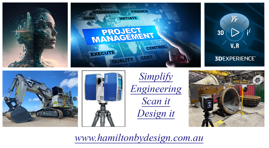
At Hamilton by Design, we specialise in turning raw site data into actionable insights. Our team uses advanced 3D scanning to capture your transfer stations with precision, builds accurate point clouds and CAD models, and runs calibrated DEM simulations to ensure your new chute design performs from day one.
Whether you’re working with coal, hard rock, or ROM ore, we help you deliver designs that fit first time, reduce maintenance headaches, and keep production running.
Contact us today to see how our integrated scanning and simulation workflow can make your next chute project safer, faster, and more reliable.
There are two things we’ve always believed at Hamilton By Design:
Accuracy matters.
If you can model it before you make it, do it.
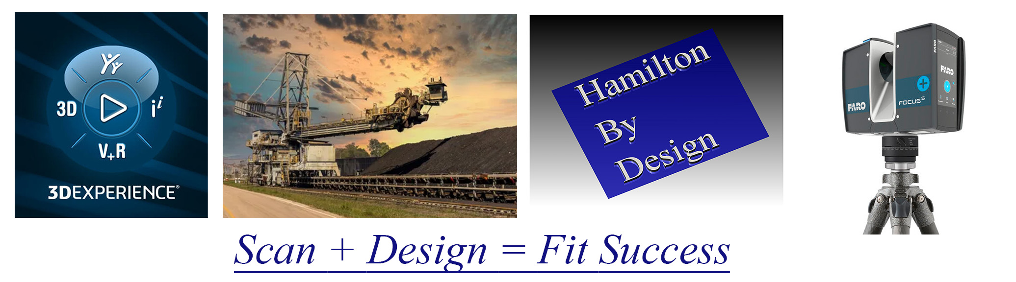
That’s why when the FARO Focus S70 hit the scene in 2017, we were early to the party — not just because it was shiny and new (though it was), but because we knew it would change how we support our clients in mining, processing, and manufacturing environments.
The S70 didn’t just give us a tool — it gave us a superpower: the ability to see an entire site, down to the bolt heads and pipe supports, in full 3D before anyone picked up a wrench. Dust, heat, poor lighting — no problem. With its IP54 rating and extended temperature range, this scanner thrives where other tools tap out.
And we’ve been putting it to work ever since.
“Measure Twice, Cut Once” Just Got a Whole Lot More Real
Laser scanning means we no longer rely on outdated drawings, forgotten markups, or that sketch someone did on the back of a clipboard in 2004.
We’re capturing site geometry down to millimetres, mapping full plant rooms, structural steel, conveyors, tanks, ducts — you name it. And the moment we leave site, we’ve already got the data we need, registered and ready to drop into SolidWorks.
Which, by the way, we’ve been using since 2001.
Yes — long before CAD was cool, we were deep into SolidWorks building models, simulating loads, tweaking fit-ups, and designing smarter mechanical solutions for complex environments. It’s the other half of the story — scan it, then model it, all in-house, all under one roof.
Safety by Design – Literally
Here’s the part people often overlook: 3D laser scanning isn’t just about accuracy — it’s about safety.
We’ve worked across enough plants and mine sites to know that the real hazards are often the things you don’t see in a drawing. Tight access ways. Awkward pipe routing. Obstructions waiting to drop something nasty when a shutdown rolls around.
By scanning and reviewing environments virtually, we can spot those risks early — hazard identification before boots are even on the ground. We help clients:
Reduce time-on-site
Limit the number of field visits
Minimise exposure to high-risk zones
Plan safer shutdowns and installations
That’s a big win in any plant or processing facility — not just for compliance, but for peace of mind.
From Point Cloud to Problem Solved
Since 2017, our scanning and modelling workflows have supported:
Brownfield upgrade projects
Reverse engineering of legacy components
Fabrication and installation validation
Creation of digital twins
Asset audits and documentation updates
And when you pair that with 24 years of SolidWorks expertise, you get more than just a pretty point cloud — you get practical, buildable, fit-for-purpose engineering solutions backed by deep industry knowledge.
Thinking about your next project? Let’s make it smarter from the start.
We’ll scan it, model it, and engineer it as we have been doing for decades — with zero guesswork and full confidence.