Hunter Valley Laser Scanning: Transforming Engineering Accuracy Across Mining, Manufacturing and Infrastructure

The Hunter Valley stands as one of Australia’s most important industrial regions, supporting mining, energy, heavy fabrication, processing, manufacturing and major commercial development. Across this diverse landscape, one challenge consistently affects project performance: the need for accurate, reliable and up-to-date site information.

For engineers, maintenance planners, fabricators and construction managers, relying on outdated drawings or manual tape measurements introduces unnecessary risk. Plants evolve over decades. Structures deform. Equipment shifts alignment. Site conditions rarely match legacy documentation.

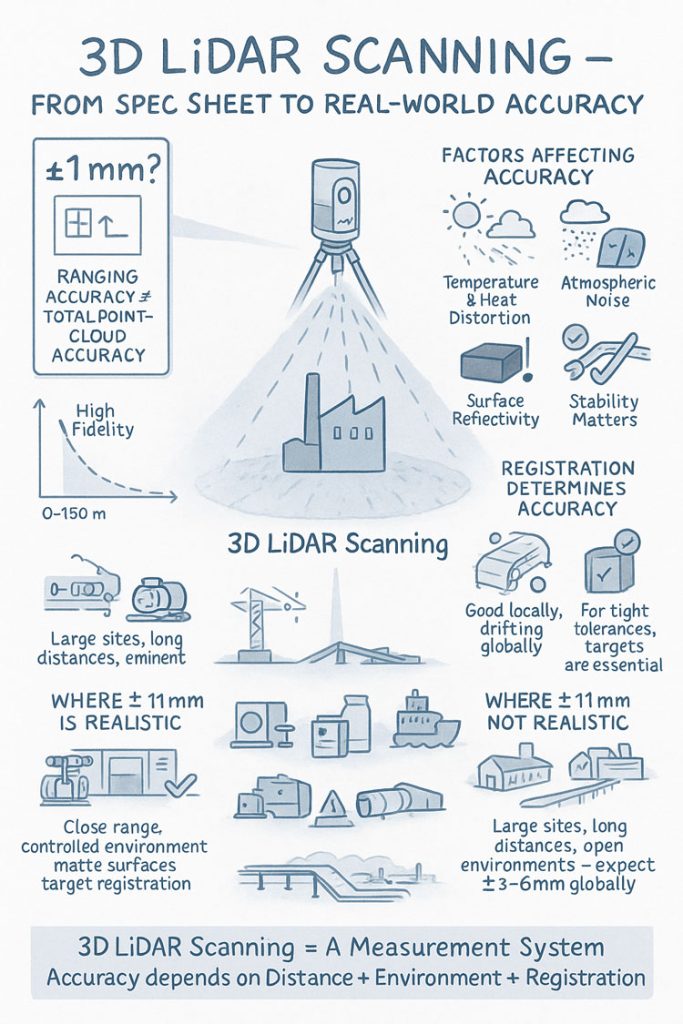
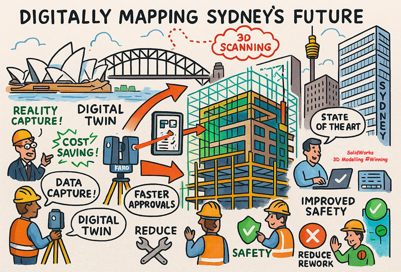
This is why Hunter Valley laser scanning has become essential. The ability to capture millimetre-accurate as-built data is transforming how projects are planned, designed and executed—reducing cost, increasing safety and ensuring that every component fits the first time.

Hamilton By Design is proud to support the region with advanced, engineering-grade laser scanning services designed specifically for heavy industry and complex brownfield environments. This article explores how laser scanning works, why the Hunter Valley relies on it, and how it strengthens everything from shutdown planning to fabrication accuracy.


Why the Hunter Valley Depends on Laser Scanning

The Hunter’s operating assets are large, complex and often decades old. Across mines, processing facilities, power stations, port handling infrastructure and manufacturing plants, very few sites match their original drawings.

Typical challenges include:

  • Numerous undocumented modifications
  • Wear, deformation and structural movement
  • Limited or unreliable legacy drawings
  • Tight shutdown windows
  • Hazardous access for manual measuring
  • Brownfield constraints that complicate upgrades

These conditions make traditional measurement methods slow, risky and error-prone. A wrong measurement in a transfer tower, a misaligned conveyor frame, or an incorrect chute dimension can create thousands of dollars in rework and delay.

Hunter Valley laser scanning eliminates these risks completely by capturing the site exactly as it exists today—not as it was decades ago.


How Hunter Valley Laser Scanning Works

Laser scanning uses high-precision LiDAR technology to record millions of data points across structures, equipment and plant areas. These points combine to create a three-dimensional “point cloud”—a highly accurate digital representation of real-world conditions.

The Hamilton By Design workflow typically includes:

1. On-Site Reality Capture

Our laser scanner is deployed across key vantage points to capture the full environment, including:

  • Structural steel
  • Conveyors and walkways
  • Chutes, bins, hoppers and material-handling equipment
  • Pipework networks
  • Equipment footprints
  • Building geometry
  • Confined or elevated spaces

The capture process is fast, safe and non-intrusive—ideal for operational sites.

2. Registration & Point Cloud Processing

Data from each scan position is aligned into a complete, unified point cloud representing the entire area with millimetre accuracy.

3. Modelling & Analysis

From the point cloud we can create:

  • True as-built CAD models
  • Structural layouts
  • Mechanical assemblies
  • Pipework geometry
  • Digital templates for fabrication
  • Probe measurements for checking clearances and alignment

4. Engineering & Fabrication Support

Once converted into a usable engineering environment, the data supports:

  • Shutdown planning
  • Structural redesign
  • Chute and conveyor optimisation
  • Digital fit checks
  • Fabrication drawings
  • Reverse engineering of worn components

The result is a reliable, verified understanding of your site—available digitally to your entire project team.


Where Hunter Valley Laser Scanning Delivers the Most Value

The unique industrial profile of the Hunter Valley means laser scanning is useful across a broad range of applications. Here are the areas where it delivers the highest impact.


Mining & CHPP Operations

Mining infrastructure in the region is constantly under pressure to operate safely and efficiently. For CHPP upgrades, conveyor realignments, chute replacements and structural modifications, laser scanning provides:

  • True as-built dimensions
  • Clearances and offset measurements
  • Verified alignment data
  • Digital templates for safe, accurate fabrication
  • Reduced shutdown duration
  • Fewer fitment issues onsite

Upgrades become predictable instead of stressful, and fabricators can manufacture with confidence.


Processing Plants & Material-Handling Systems

Transfer towers, bin replacements, screening arrangements and crusher areas often contain congested layouts with poor access. Manual measurement is difficult and unsafe.

Laser scanning solves this by allowing the entire environment to be measured remotely. This supports:

  • Clash prevention
  • Redesign of worn systems
  • Smoother installation
  • Accurate interface points
  • Digital verification before fabrication

Heavy Fabrication & Workshop Integration

Fabricators across the Hunter Valley consistently face the same problem: components not fitting onsite due to bad measurements.

Hunter Valley laser scanning ensures:

  • Perfectly matched bolt hole patterns
  • Correct flange alignment
  • True geometry of mating parts
  • Accurate templates for bending, rolling and welding
  • Reduced rework and scrap

It is a direct cost saver for both workshops and clients.


Energy, Power Stations & Utilities

Power stations and energy sites require sophisticated maintenance planning. Laser scanning helps engineers:

  • Document aging structures
  • Compare deformation over time
  • Plan retrofits and upgrades
  • Replace platforms, pipework and supports with confidence
  • Identify clashes before installation

This improves compliance and reduces risk.


Commercial, Industrial and Infrastructure Projects

Beyond heavy industry, the Hunter region features growing precincts of commercial and industrial developments. Laser scanning supports:

  • Renovations and extensions
  • As-built documentation
  • BIM workflows
  • Accurate drafting and facility mapping

It ensures architects, builders and property owners are working with verified building conditions instead of assumptions.


Why Choose Hamilton By Design for Hunter Valley Laser Scanning?

Hamilton By Design is not simply a scanning service—we are engineers first. This is what sets our work apart.

Our Engineering Mindset

We understand plant design, structural requirements, chute behaviour, mechanical layouts and fabrication constraints. This allows us to interpret the point cloud with engineering intent, not just technical detail.

Millimetre Accuracy

Our laser scanning systems deliver the precision required for heavy industry, ensuring designs and fabrication match the real-world geometry exactly.

Complete Digital Workflow

We provide:

  • Point clouds
  • 3D models
  • General arrangement drawings
  • Fabrication drawings
  • DXFs and model exports

Our deliverables integrate seamlessly with fabrication shops and engineering teams across the Hunter.

Local Expertise

We understand the region’s industries, shutdown pressures, safety expectations and operational challenges.

Confidence Before Steel Is Cut

Every design can be checked digitally for clash, alignment and fitment—reducing uncertainty and rework.


The Future of Engineering in the Hunter Valley

As sites age and operational demands increase, precise as-built information is becoming essential. Hunter Valley laser scanning is now the standard for safe, efficient and accurate engineering work across the region.

Whether you are replacing structural steel, redesigning a chute, installing new conveyors, upgrading a plant room or fabricating new components, laser scanning gives your project the foundation it needs for success.


Work With Hamilton By Design

Hamilton By Design is ready to support your next project with high-accuracy Hunter Valley laser scanning, modelling and drafting services.

Contact our team to discuss:

  • Your scanning requirements
  • Project constraints
  • Fabrication goals
  • Engineering support needs

We will help you build a digital foundation that improves safety, reduces downtime and ensures every component fits the first time.

Hamilton By Design logo displayed on a blue tilted rectangle with a grey gradient background

3D Scanning in The Hunter Valley

Enhancing Plant Efficiency with Best Maintenance Practices

3D Point Clouds Are a Game-Changer for Your Projects

Lessons from a Landmark Case

The Real-World Accuracy of 3D LiDAR Scanning With FARO S150 & S350 Scanners

When people first explore 3D LiDAR scanning, one of the most eye-catching numbers in any product brochure is the advertised accuracy. FARO’s Focus S150 and S350 scanners are often promoted as delivering “±1 mm accuracy,” which sounds definitive and easy to rely on for engineering, mining and fabrication work. But anyone who has spent time working with 3D LiDAR scanning in real industrial environments understands that accuracy isn’t a single number — it is a system of interrelated factors.

This article explains what the ±1 mm specification from FARO really means, how accuracy shifts with distance, and what engineers, project managers and clients need to do to achieve dependable results when applying 3D LiDAR scanning on live sites.


Infographic explaining 3D LiDAR scanning accuracy, showing a scanner capturing a building and highlighting factors that affect accuracy such as temperature, atmospheric noise, surface reflectivity and tripod stability. Includes diagrams comparing realistic versus unrealistic ±1 mm accuracy, the impact of distance, environment and registration quality, and notes that large open sites typically achieve ±3–6 mm global accuracy.

1. What FARO’s “±1 mm Accuracy” Really Means in 3D LiDAR Scanning

The ±1 mm number applies only to the internal distance measurement unit inside the scanner. It reflects how accurately the laser measures a single distance in controlled conditions.

It does not guarantee:

  • ±1 mm for every point in a full plant model
  • ±1 mm for every dimension extracted for engineering
  • ±1 mm global accuracy across large multi-scan datasets

In 3D LiDAR scanning, ranging accuracy is just one ingredient. Real-world accuracy is shaped by distance, reflectivity, scan geometry and how multiple scans are registered together.


2. How Accuracy Changes With Distance in Real Projects

Even though the S150 and S350 list the same ranging accuracy, their 3D LiDAR scanning performance changes as distance increases. This is due to beam divergence, angular error, environment and surface reflectivity.

Typical real-world behaviour:

  • 0–10 m: extremely precise, often sub-millimetre
  • 10–25 m: excellent for engineering work, only slight noise increase
  • 25–50 m: more noticeable noise and increasing angular error
  • 50–100 m: atmospheric distortion and reduced overlap become evident
  • Near maximum range: still useful for mapping conveyors, yards and structures, but not suitable for tight fabrication tolerances

This distance-based behaviour is one of the most important truths to understand about 3D LiDAR scanning in field conditions.


3. Ranging Accuracy vs Positional Accuracy vs Global Accuracy

Anyone planning a project involving 3D LiDAR scanning must distinguish between:

Ranging Accuracy

The ±1 mm value — only the distance measurement.

3D Positional Accuracy

The true X/Y/Z location of a point relative to the scanner.

Global Point Cloud Accuracy

How accurate the entire dataset is after registration.

Global accuracy is the number engineers depend on, and it is normally around ±3–6 mm for large industrial sites — completely normal for terrestrial 3D LiDAR scanning.


4. What Real Field Testing Reveals About FARO S-Series Accuracy

Independent practitioners across mining, infrastructure, CHPPs, plants and structural environments report similar results when validating 3D LiDAR scanning against survey control:

  • ±2–3 mm accuracy in compact plant rooms
  • ±5–10 mm across large facilities
  • Greater drift across long, open, feature-poor areas

These outcomes are not equipment faults — they are the natural result of how 3D LiDAR scanning behaves in open, uncontrolled outdoor environments.


5. Why Registration Matters More Than the Scanner Model

Most real-world error in 3D LiDAR scanning comes from registration, not the laser itself.

Cloud-to-Cloud Registration

Good for dense areas, less reliable for long straight conveyors, open yards or tanks.

Target-Based Registration

Essential for high-precision engineering work.
Allows tie-in to survey control and dramatically improves global accuracy.

If your project needs ±2–3 mm globally, target control is mandatory in all 3D LiDAR scanning workflows.


6. Surface Reflectivity and Environmental Effects

Reflectivity dramatically affects measurement quality during 3D LiDAR scanning:

  • Matte steel and concrete return excellent data
  • Rusted surfaces return good data
  • Dark rubber, black plastics and wet surfaces reduce accuracy
  • Stainless steel and glass behave unpredictably

Environmental factors — wind, heat shimmer, dust, rain — also reduce accuracy. Early morning or late afternoon typically produce better 3D LiDAR scanning results on mining and industrial sites.


7. When ±1 mm Is Actually Achievable

True ±1 mm accuracy in 3D LiDAR scanning is realistic when:

  • Working within 10–15 m
  • Surfaces are matte and reflective
  • Registration uses targets
  • Tripod stability is high
  • Conditions are controlled

This makes it suitable for:

  • Pump rooms
  • Valve skids
  • Structural baseplates
  • Reverse engineering
  • Small mechanical upgrades

But achieving ±1 mm across a full plant, CHPP, or yard is outside the capability of any terrestrial 3D LiDAR scanning workflow.


8. S150 vs S350: Which One for Your Accuracy Needs?

S150 – Engineering-Focused Precision

Ideal for industrial rooms, skids, structural steel and retrofit design work where short-to-mid-range accuracy is essential.

S350 – Large-Area Coverage

Perfect for conveyors, rail lines, yards, and outdoor infrastructure.
Global accuracy must be survey-controlled for tight tolerances.

Both scanners deliver excellent 3D LiDAR scanning performance, but the S150 is the engineering favourite while the S350 is the large-site specialist.


9. What to Specify in Contracts to Avoid Misunderstandings

Instead of stating:

“Scanner accuracy ±1 mm.”

Specify:

  • Local accuracy requirement (e.g., ±2 mm at 15 m)
  • Global accuracy requirement (e.g., ±5 mm total dataset)
  • Registration method (mandatory target control)
  • Environmental constraints
  • Verification method (e.g., independent survey checks)

This ensures everyone understands what 3D LiDAR scanning will realistically deliver.


10. When a Terrestrial Scanner Is Not Enough

Do not rely solely on 3D LiDAR scanning for:

  • Machine alignment <1 mm
  • Bearing or gearbox placement
  • Certified dimensional inspection
  • Metrology-level tolerances

In these cases, supplement scanning with:

  • Laser trackers
  • Total stations
  • Metrology arms
  • Hybrid workflows

Conclusion: The Real Truth About 3D LiDAR Scanning Accuracy

FARO’s S150 and S350 are outstanding tools for industrial 3D LiDAR scanning, but the ±1 mm spec does not tell the full story. Real-world accuracy is a combination of:

  • Distance
  • Registration method
  • Surface reflectivity
  • Site conditions
  • Workflow discipline

When used correctly, these scanners consistently deliver high-quality, engineering-grade point clouds suitable for clash detection, retrofit design, fabrication planning and as-built documentation.

3D LiDAR scanning is not just a laser — it is an entire measurement system.
And when the system is applied with care, it produces reliable, repeatable data that reduces rework, improves safety, and strengthens decision-making across mining, construction, fabrication and industrial operations.

Where Is your project

3D Scanning Sydney CBD3D Scanning Brisbane CBD
3D Scanning across Melbourne3D Scanning across Perth
3D Scanning across Adelaide3D Scanning in The Hunter Valley
3D Scanning Mount Isa3D Scanning Emerald
3D Laser Scanning Central Coast3D Scanning in The Pilbara
3d Scanning other Areas of Australia3D Scanning Outside Australia
Hamilton By Design logo displayed on a blue tilted rectangle with a grey gradient background
Name
You would like to:

3D CAD Modelling | 3D Scanning

3D Experience Platform Login

3D Scanning for Construction

Transforming Projects with 3D Scanning

3D LiDAR Scanning – Digital Quality Assurance

Building Sydney Smarter: How 3D Scanning and LiDAR Are Transforming Construction Accuracy

A New Era of Construction Accuracy in Sydney

Sydney’s construction industry is booming — from commercial towers and infrastructure upgrades to industrial developments and complex refurbishments. But as sites become more congested and designs more complex, achieving perfect alignment between fabricated and installed components has never been more challenging.

That’s where 3D scanning and LiDAR technology come in. At Hamilton By Design, we provide high-precision digital capture and 3D modelling services that ensure every element of your construction project fits seamlessly together, saving time, cost, and effort onsite.


Capturing the Real Site with LiDAR Scanning

Using LiDAR (Light Detection and Ranging) scanners, we capture millions of laser measurements per second to create an exact 3D digital record — known as a point cloud — of your construction site or structure.

This means we can document existing conditions, monitor progress, and verify installations with millimetre-level precision. For Sydney builders, engineers, and contractors, that data eliminates the guesswork and drastically reduces costly clashes and rework later on.


From Point Cloud to 3D Model

Once the LiDAR data is captured, it’s processed into detailed 3D CAD and BIM models compatible with leading design software such as Revit, AutoCAD, SolidWorks, and Navisworks.

These accurate models allow design teams to:

  • Validate and update as-built conditions before fabrication
  • Detect clashes and misalignments before installation
  • Plan modifications and extensions with confidence
  • Coordinate between mechanical, structural, and architectural disciplines

By working from a true digital twin of your Sydney site, you can be sure every part — from prefabricated frames to pipe runs — will fit exactly where it should.


Why Sydney Construction Projects Are Turning to 3D Scanning

  • Reduced Rework: Identify design and fabrication issues before they reach site.
  • Improved Safety: Capture high or restricted areas without scaffolding or shutdowns.
  • Shorter Installation Times: Minimise downtime and delays during fit-up.
  • Precise Documentation: Maintain accurate records for QA and handover.
  • Better Collaboration: Integrate real-world data into your BIM environment.

From commercial fit-outs to infrastructure projects across Greater Sydney, 3D scanning provides a single source of truth for every stakeholder.


Typical Sydney Projects Using LiDAR and 3D Modelling

Hamilton By Design supports a range of construction and engineering clients, including:

  • Commercial and residential developments in the CBD and inner suburbs
  • Industrial plant upgrades across Western Sydney
  • Transport and infrastructure projects under NSW Government programs
  • Refurbishment and brownfield works requiring detailed as-built verification

Each project benefits from faster delivery, greater precision, and stronger communication between designers, builders, and clients.


Partner with Hamilton By Design

If you’re working on a Sydney construction or infrastructure project and need accurate 3D site data, as-built modelling, or fit-up verification, Hamilton By Design can help.

Our experienced mechanical and design specialists combine field scanning with advanced 3D modelling to deliver practical, reliable results that make construction smoother — and smarter.

Mechanical Engineers in Sydney

Hamilton By Design Logo www.hamiltonbydesign.com.au
Hamilton By Design logo displayed on a blue tilted rectangle with a grey gradient background

Mechanical Engineering | Structural Engineering

3D Scanning Sydney

Engineering Services

get in touch

sales@hamiltonbydesign.com.au

📍 Based in Sydney — working across NSW and Australia
📧 info@hamiltonbydesign.com.au
🌐 www.hamiltonbydesign.com.au

Capture. Model. Verify. Deliver — precision that builds Sydney better.