When Local Knowledge Makes All the Difference
Across Sydney, the Central Coast, and Newcastle, more contractors and plant managers are discovering a simple truth — offshore engineering might look cost-effective, but local expertise delivers better outcomes every time.
When drawings don’t meet Australian Standards, materials can’t be sourced locally, or site measurements are off by just a few millimetres, “cheap” design quickly becomes expensive rework.
That’s why businesses across NSW are turning to Hamilton By Design — a Sydney-based mechanical engineering practice that understands how to bridge design and construction through real-world experience, compliance, and precision.
Built for Australia, Not Adapted for It
Engineering design isn’t universal.
Sydney’s environment, industry, and regulatory framework are unique — from local council approval requirements to the coastal conditions that affect corrosion and material selection.
At Hamilton By Design, our drawings and models are created with Australian Standards front and centre. We design for:
- AS 4100 (Steel Structures)
- AS 3990 (Mechanical Equipment Design)
- AS 1657 (Walkways, Platforms & Stairs)
- AS 4991 (Lifting Devices)
- AS 4024 (Machine Safety)
Designing to these standards means your project moves faster through approvals, fabrication, and certification — with no surprises down the track.
Offshore designers often mean well, but they don’t work within these standards every day.
A single misinterpreted load case or welding symbol can mean days of rework on site.
A local engineer gets it right the first time.
Drawings That Fabricators Love
A good drawing doesn’t just look professional — it saves hours in the workshop.
Hamilton By Design creates fabrication drawings that make sense to the people who use them.
We think like tradespeople because we’ve been tradespeople.
Our background in fitting, machining, and CNC fabrication ensures every detail — from weld prep to bolt clearances — reflects how the job will actually be built.
That means fewer questions from the shop floor, cleaner fit-ups, and faster turnaround from fabrication to installation.

Local Materials. Local Supply Chains. Fewer Delays.
Sydney’s fabrication and construction industry runs on locally available materials — from Bluescope steel to Bisalloy plate.
When offshore drawings specify unavailable materials or imperial sizes, fabrication stalls.
Our team specifies components, sections, and finishes that Sydney and Central Coast suppliers actually stock.
That reduces lead times, avoids substitutions, and keeps projects moving.
We also design with Sydney’s coastal environment in mind — using corrosion-resistant coatings, sealants, and fasteners suitable for marine-influenced locations like Parramatta, Botany, and Gosford.
Designed to Fit the Site — The First Time
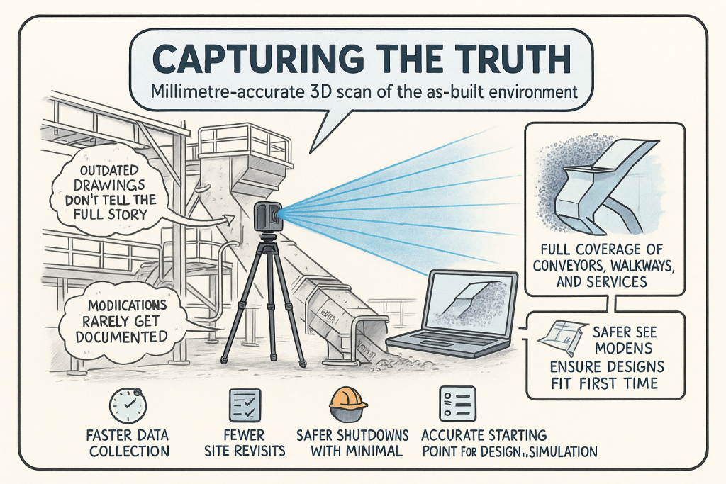
It’s one thing to design in CAD; it’s another to make it fit in the field.
Sydney worksites can be complex — restricted access, uneven terrain, or legacy structures that don’t match the old drawings.
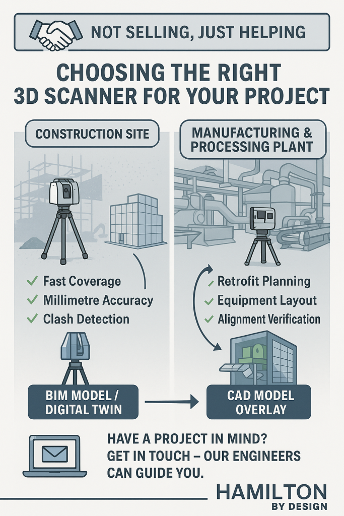
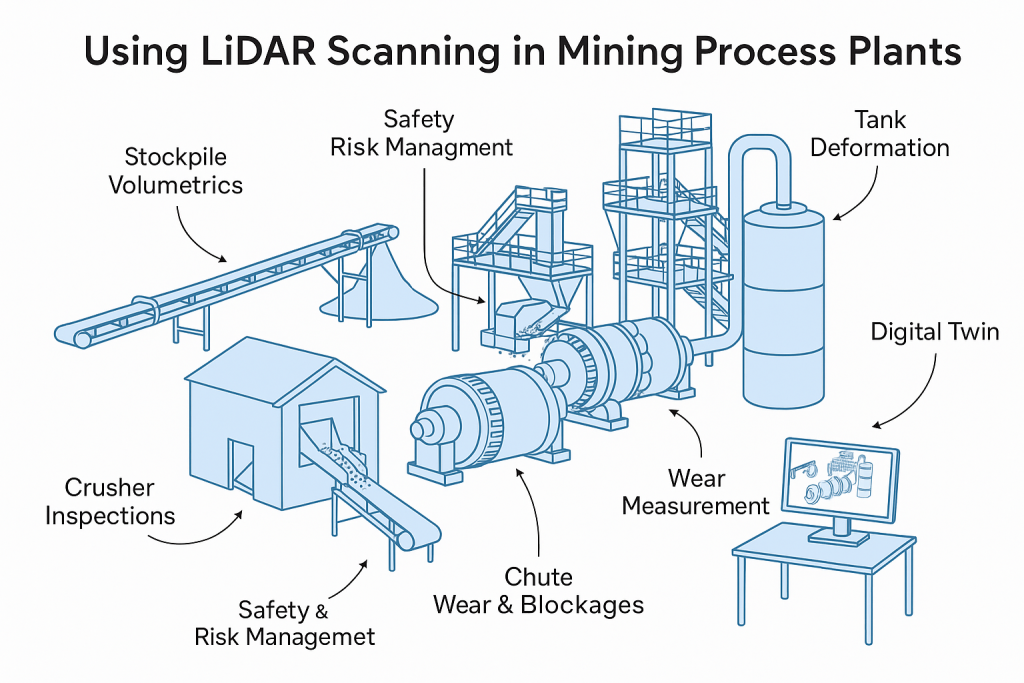
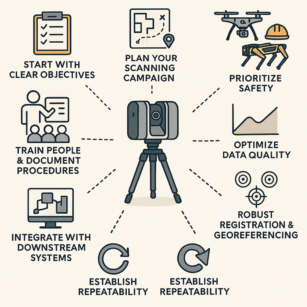
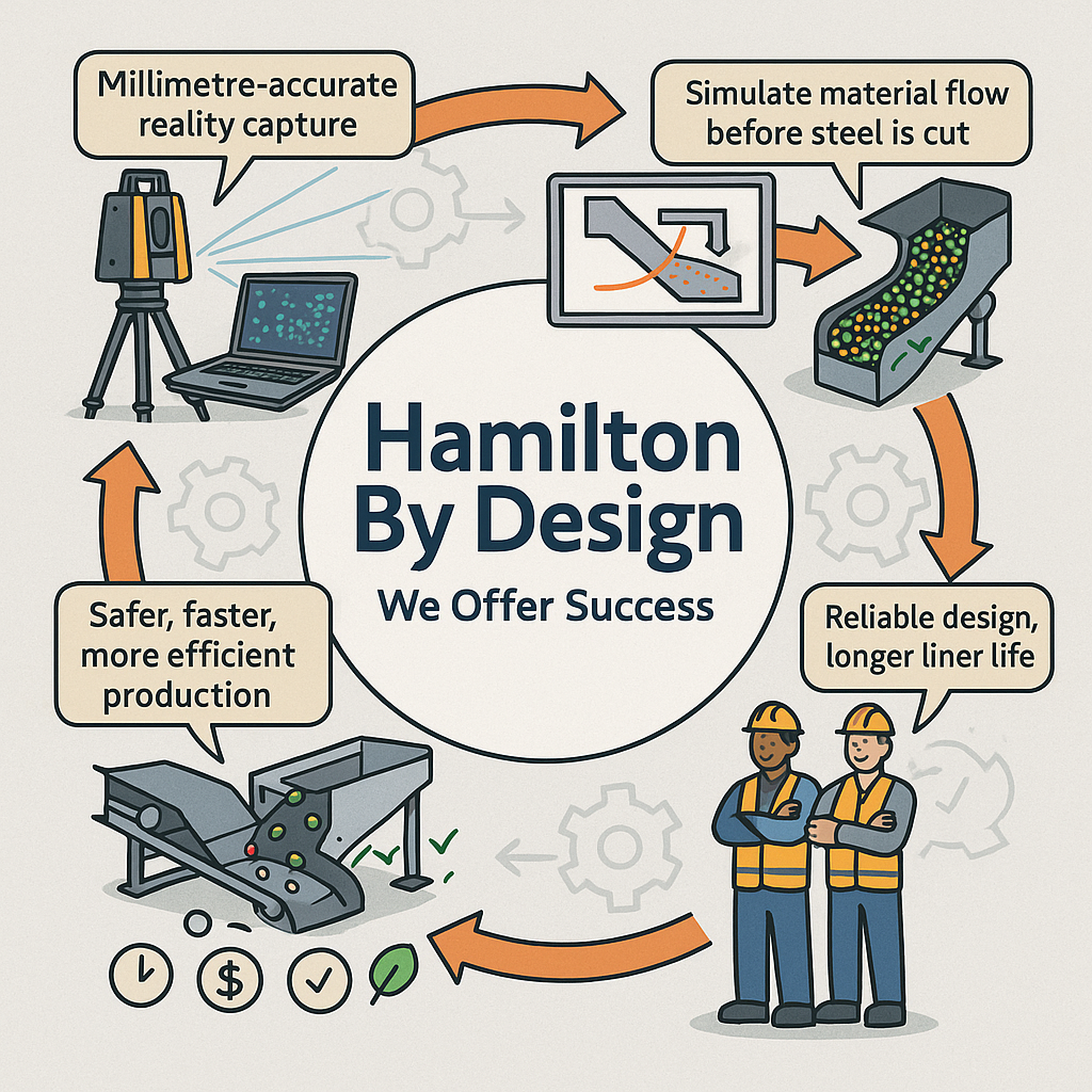
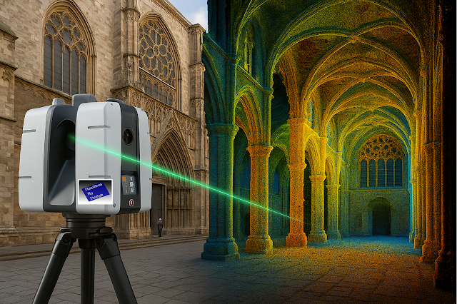
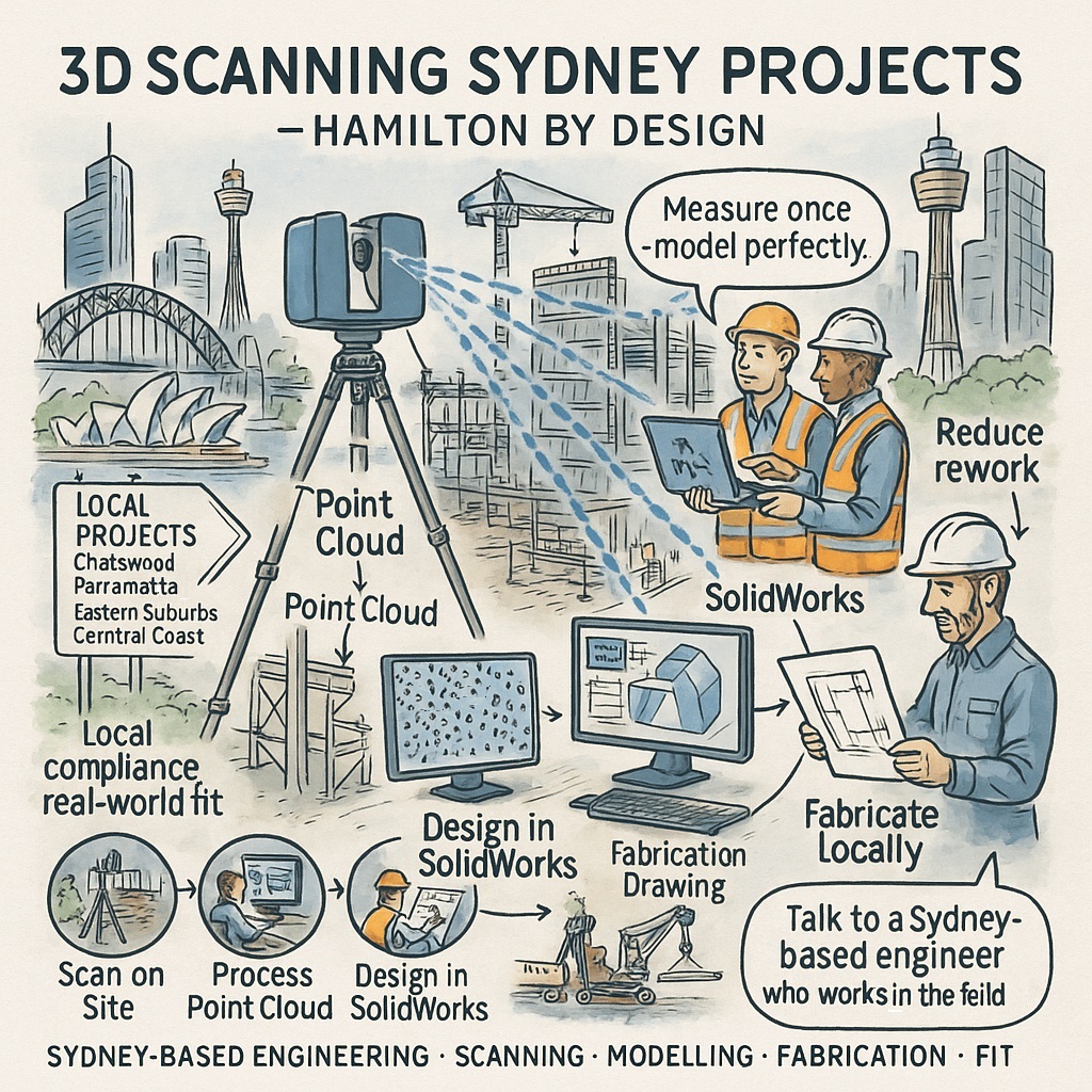
That’s why Hamilton By Design uses 3D scanning and LiDAR technology to capture accurate site data before design begins.
We integrate those scans directly into SolidWorks, building models that align with real-world geometry.
Every bracket, pipe run, and platform is verified in 3D before fabrication starts — ensuring a smooth installation with no rework.
Sydney Expertise with Regional Reach
We proudly serve clients across Sydney, Newcastle, and the Central Coast, working with builders, maintenance contractors, and fabrication workshops who value local knowledge.
Our typical projects include:
- Plant upgrades and retrofits in brownfield sites.
- Fabrication drawing packages for chutes, platforms, and pipework.
- Reverse engineering from worn or obsolete components.
- 3D scanning for as-built documentation.
- Finite Element Analysis (FEA) for structural verification.
Every project benefits from our combined trade and engineering background — practical solutions grounded in decades of hands-on experience.
Smooth Communication. Real Accountability.
When you work with a local engineer, you’re not waiting overnight for an email response from another time zone.
You can pick up the phone, meet on site, or review models in person.
That direct collaboration saves time, reduces misunderstandings, and builds confidence between all stakeholders — engineers, fabricators, and project managers alike.
At Hamilton By Design, we value clear communication. You’ll know exactly what stage your project is at, what we’re designing, and how it aligns with your goals.
The Real Cost of Offshore Design
Offshore pricing often looks appealing — until you factor in delays, non-compliance, or fabrication mismatches.
Here’s what typically happens when projects cut corners:
| Challenge | Offshore Design | Local Expertise (Hamilton By Design) |
|---|---|---|
| Standards & Codes | Often missed or misapplied | Fully compliant with AS/NZS standards |
| Material Availability | Specified incorrectly | Designed for Australian supply chains |
| Communication | Delayed and unclear | Direct, same-day response |
| Site Understanding | Based on photos | Based on 3D scans and site visits |
| Rework Risk | High | Minimal – verified before fabrication |
When you calculate the true cost — lost time, rework, freight, and approval delays — offshore design rarely saves money.

Real Example: Central Coast Fabrication Success
A local contractor recently engaged Hamilton By Design to assist with a pump platform upgrade on the Central Coast.
Previous offshore drawings had mismatched hole patterns and unsupported loads.
We performed a quick 3D scan, remodelled the assembly in SolidWorks, and issued fabrication drawings ready for workshop production.
The new structure was installed without modification, saving the client several days of rework and earning rapid certifier approval.
That’s what local insight delivers — certainty and speed.
Why Choose a Sydney-Based Engineer
Sydney projects move quickly.
They need partners who can respond fast, understand the regulations, and coordinate seamlessly with site teams.
Hamilton By Design offers:
✅ Over 25 years of trade and design experience
✅ SolidWorks and FEA capability since 2011
✅ 3D scanning and as-built modelling for existing plants
✅ Fabrication drawings built for local workshops
✅ Practical designs created by people who’ve worked in the field
We’re based in Sydney and proud to support regional clients in Newcastle, the Central Coast, and Western Sydney.
Talk to a Sydney-Based Engineer Who’s Worked in the Field
Every project is a partnership — and great results come from working with people who understand your environment.
Hamilton By Design isn’t just another design service; we’re your local mechanical engineering partner — practical, responsive, and invested in your success.
If you’re planning a plant upgrade, mechanical installation, or fabrication project, let’s make sure your drawings are done right the first time.
👉 Talk to a Sydney-based engineer who’s worked in the field.
Visit www.hamiltonbydesign.com.au or contact us today to discuss your next project.