Next-Generation 3D Modelling & Scanning Advances in 2025

Illustrated infographic titled “Recent Advancements in 3D Modelling and 3D Scanning.” It features four themed sections around a central title. “Enhanced Performance” shows a person working on a computer with faster response times for complex parts and assemblies. “Improved Collaboration” depicts two people discussing streamlined design communication. “Streamlined Workflows” shows a microscope and gears representing improved management of part, assembly, and drawing processes. “Richer Scan Data” shows a technician scanning an object and a computer displaying a dense point cloud model, emphasising greater accuracy and data density. The overall image highlights modern improvements in modelling, collaboration, workflows, and point cloud scanning.

1. Collaboration and Data Management

Collaboration is increasingly centred around 3D data. Modern platforms now let teams review, comment on, and markup native 3D models directly inside the design environment. Instead of relying solely on screenshots or static drawings, stakeholders can spin, section, and measure live models for better context. Real-time update notifications and cloud-connected revision control ensure that scanned 3D data and parametric CAD models stay synchronized — critical when working with reality capture data that represents the as-built environment. Hybrid data management options combine local PDM systems with cloud platforms, supporting distributed teams handling massive point clouds or mesh data. This tight integration means that model changes — whether from new design iterations or updated scans — propagate instantly across the project team. Decision-making becomes more visual and informed, keeping everyone aligned around a single, authoritative 3D dataset. Collaboration is no longer a separate process but embedded into daily 3D workflows.


2. Smarter Part Modelling

3D modelling tools are now more intelligent and better suited for working with scan-derived geometry. Designers can quickly apply chamfers, fillets, and shells across complex surfaces, even those imported from meshes or point cloud extractions. Automated bend notch creation and sheet metal tools are optimized to work with geometry derived from scanning existing parts, making reverse-engineering and fabrication preparation much faster. Reference geometry patterning allows engineers to build parametric frameworks over point cloud regions, speeding up master model creation. Cleanup utilities now support selectively removing unnecessary features or smoothing noisy scan data without rebuilding the entire model history. These advances turn what used to be a labour-intensive process into a streamlined workflow that transforms raw reality capture data into production-ready models. The focus is on reducing friction between physical and digital — allowing engineers to move quickly from scan to design, then to manufacturing.


3. Large Assembly Performance

Point cloud and mesh datasets are often extremely large, so performance improvements are critical. Modern CAD platforms now handle assemblies containing both traditional parametric models and massive scan data without bringing systems to a crawl. Engineers can duplicate components while maintaining mates, overlay scans onto assemblies to check fit, and perform interference detection even in lightweight modes. Visualization performance has been tuned for high-density point clouds, allowing smooth pan, zoom, and rotate interactions even with billions of points. Simplification and decimation tools let users strip out unneeded scan detail for faster load times while retaining critical geometry. Seamless transitions between lightweight review and full edit mode make it possible to work interactively with scanned environments. This capability is especially valuable for plant layout, construction validation, and retrofitting projects, where the ability to handle large, mixed-format 3D datasets directly within assemblies is a competitive advantage.


4. Enhanced Drawings and Documentation

Although 3D is the primary medium, 2D documentation remains essential — especially for suppliers and manufacturing partners. Modern CAD environments generate drawings directly from parametric models or scan-based reconstructions, ensuring that documentation matches the latest as-built conditions. Multi-approval stamps, BOM quantity overrides, and standards compliance tools make it easy to document parts created from reverse engineering or field measurement data. Automatic view generation and model-based definition (MBD) help reduce the reliance on fully manual drawings, embedding dimensions and tolerances directly into the 3D model where possible. For projects using scans, section views can be cut through the point cloud or mesh to produce accurate reference drawings without redrawing geometry. These improvements ensure that documentation is both faster to produce and more accurate — giving fabrication teams confidence that the deliverables reflect real-world conditions rather than idealized design intent.


5. Seamless ECAD/MCAD Integration

The convergence of 3D scanning and electronics integration is enabling more precise mechatronic design. Point cloud models of housings, enclosures, and factory floors can be combined with PCB outlines and component data for fit validation. Modern tools allow importing copper traces, vias, and keep-out regions into the mechanical model to run thermal or clearance checks directly against scanned geometry. This prevents collisions and ensures proper heat management early in the design cycle. Real-time synchronization between ECAD and MCAD domains means that if a scanned housing reveals unexpected tolerances, electrical designers can adjust their board layout accordingly. The result is a more accurate digital twin that accounts for both the designed and as-built states. This tighter integration avoids costly late-stage changes, shortens time-to-market, and ensures that mechanical and electrical systems are developed with a shared, reliable 3D reference that reflects physical reality.


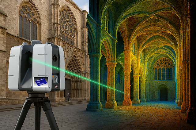
6. Performance and Visualization

Visualization is where 3D scanning truly shines. GPU-accelerated engines now render massive point clouds, meshes, and parametric geometry in real time, allowing teams to virtually “walk through” captured environments or inspect reverse-engineered parts at full fidelity. Silhouette-based defeature tools can strip away irrelevant details while maintaining enough geometry for accurate reviews and clash detection. Cached mass property calculations extend to mesh and hybrid models, giving accurate weight and center of gravity data even from scan-derived parts. Photorealistic rendering using real-time ray tracing allows stakeholders to experience designs exactly as they will look, bridging the gap between scanned reality and proposed modifications. This level of visual fidelity improves collaboration, reduces the need for physical mock-ups, and accelerates stakeholder buy-in. High-quality 3D visualization is no longer a luxury — it is a daily tool for engineers, designers, and decision-makers alike.


7. Future Outlook

The future of 3D modelling is increasingly driven by AI and reality capture. Expect CAD platforms to automatically recognize features within point clouds — holes, slots, threads — and generate parametric features with minimal user input. Cloud-native workflows will make it easier to process extremely large scan datasets without local performance bottlenecks. Automated drawing generation and model-based definition will continue to reduce documentation overhead, while digital twin technology will tie live sensor data to scanned geometry for ongoing validation. Generative design powered by AI will be able to work directly with scanned environments, proposing optimized solutions that account for real-world constraints. This convergence of scanning, modelling, and simulation promises a future where physical and digital coexist seamlessly — enabling engineers to capture, design, simulate, and validate with unprecedented speed and accuracy, ultimately transforming how products, factories, and infrastructure are created and maintained.

Hamilton By Design logo displayed on a blue tilted rectangle with a grey gradient background

3D Modelling | 3D Scanning | Point Cloud Scanning

3D Laser Scanning of Hotels

3d laser scanning for engineering

3D Scanning for Construction in Sydney

Why 3D Point Clouds + Expert Modelers Are a Game-Changer for Your Projects

Infographic illustrating the 3D project data workflow, showing LiDAR scanners and drones capturing millions of data points, a designer modelling on a computer, and project teams validating accurate 3D data, highlighting benefits such as speed, accuracy, cost savings and project success.

Level Up your 3D Scans

In today’s world, accuracy and efficiency can make or break a project. Whether you’re working in architecture, construction, engineering, or product design, you need reliable data — and you need it fast. That’s where 3D point clouds come in.

But there’s an important catch: not all scans are created equal. The difference between an average scan and a great one often comes down to the person behind the scanner. Having someone who understands 3D modeling take the scans can dramatically improve your project’s accuracy, reliability, and overall success.

Let’s break down why.


The Power of 3D Point Clouds

Point clouds are essentially millions of tiny data points that capture the shape of an object, room, or entire site. Together, they create a highly detailed digital snapshot of the real world.

Here’s why this matters:

  • Precision you can trust – Point clouds deliver incredibly detailed measurements, capturing even the smallest curves and angles.
  • Nothing gets missed – Multiple scan angles ensure a full, 360° view of your site or object.
  • Speed and efficiency – What used to take hours (or days) with manual measurements can be captured in minutes.
  • Built-in context – You’re not just getting numbers; you’re getting a complete digital environment to work inside.
  • Future-proof data – Once you have a scan, you have a permanent record of your space, ready to use months or years later.

From clash detection to as-built verification, point clouds save time, reduce errors, and make collaboration across teams smoother than ever.


Why the Person Taking the Scan Matters

While technology is powerful, experience is what makes the results reliable. Having a skilled 3D modeler operate the scanner can be the difference between a good project and a great one.

Here’s why an expert makes all the difference:

  • They know what matters – A modeler understands which details are critical for your project and ensures they’re captured.
  • Fewer gaps, fewer surprises – Experienced pros know how to plan scan positions to cover every angle and avoid blind spots.
  • Cleaner, more accurate data – They reduce common issues like noise, misalignment, or missing sections that can throw off your model.
  • Time saved, headaches avoided – No one wants to redo a scan halfway through a project. A professional ensures you get it right the first time.
  • Confidence from start to finish – When you know your model is accurate, you can move forward with design and construction decisions without second-guessing.

In short: a great scanner operator doesn’t just deliver data — they deliver peace of mind.


The Bottom Line

3D point clouds are already transforming how projects are planned and delivered. But pairing them with an experienced 3D modeler takes things to the next level.

You’ll get better data, faster turnarounds, and a far lower risk of costly mistakes. And when your goal is to deliver projects on time, on budget, and with zero surprises, that’s an edge you can’t afford to miss.

Hamilton By Design logo displayed on a blue tilted rectangle with a grey gradient background

3D Modelling | 3D Scanning | Point Cloud Scanning

3D Scanning

How 3D Laser Scanning is Redefining Reality for Design, Construction & Heritage

Imagine standing before a centuries-old cathedral, where every carved arch, every stained-glass pane, every weathered stone holds centuries of stories. Capturing its true form and condition with tape measure and camera? Tedious and prone to errors. But with 3D laser scanning, you can digitally freeze every detail—down to the imperfections—turning reality into an exact, manipulable model.

In an age where precision, speed, and data-driven decisions are non-negotiable, 3D laser scanning is no longer “nice to have”—it’s essential. Let’s explore what it is, why it’s transformative, where it’s being used most powerfully, and how you can harness its potential.

What Is 3D Laser Scanning?

At its core, 3D laser scanning sometimes called terrestrial laser scanning, (TLS) is the emission of laser pulses toward surfaces, recording the time it takes for those pulses to bounce back. From that comes a dense “point cloud” — billions of precise data points mapping shape, texture, orientation, and distance.

These point clouds become high-fidelity models, maps, meshes, or BIM ready files. Whether you’re scanning building exteriors, interiors, or industrial components, the result is more than just imagery—it’s measurable, analyzable geometry.

How It Works — The Process

  1. Preparation & Planning

    Define what you need: the level of detail (LOD), resolution, range, and whether external conditions (light, weather) will interfere.

  2. Data Capture

    Position the scanner at multiple stations to cover all surfaces. Use targets or reference markers for alignment and capture with overlapping scans.

  3. Processing & Registration

    Merge scans to align them properly, clean noise, filter out irrelevant data (like people, moving objects), calibrate.

  4. Post-processing & Deliverables

    Convert point clouds into usable outputs—floorplans, sections, elevations, 3D meshes, BIM models, virtual walkthroughs. Run analyses (clash detection, deformation etc.).

  5. Integration & Use

    Use the data in design, restoration, facility management, or documentation. The quality of integration (into BIM, GIS, CAD) is key to unlocking value.

Key Benefits

Benefit What It Means in Practice Real-World Impact
Extreme Precision Sub-millimetre to millimetre accuracy depending on the scanner and conditions. Less rework. Better fit for retrofit, renovation, or mechanical systems in tight tolerances.
Speed + Efficiency Collect large amounts of spatial data in far less time than traditional measurement. Faster project turnaround. Reduced site time costs.
Non-Contact / Low Disruption Good for fragile structures, hazardous or difficult-to-access places. Preserves integrity of heritage buildings; safer for workers.
Comprehensive Documentation Full visual & geometric context. Informs future maintenance. Acts as an archival record.
Better Decision Making & Conflict Detection Early clash detection; scenario simulation; what-if modelling. Avoids costly mistakes; helps build consensus among stakeholders.
Enhanced Visualisation & Communication Stakeholders can see exactly what exists vs. what’s being proposed. Improves client buy-in, regulatory approvals, fundraising.

Applications: Where It Shines

  • Architecture & Renovation: As-built models, restoration of heritage sites.

  • Infrastructure & Civil Engineering: Bridges, tunnels, rail track alignments.

  • Industrial & Manufacturing: Machine part audits, reverse-engineering, plant layout.

  • Heritage & Preservation: Documenting fragile monuments, archaeological sites.

  • Facility Management: Digital twins, maintenance, asset tracking.

  • Environment & Surveying: Terrain mapping, forestry, flood risk mapping (especially when combined with aerial systems or mobile scanning).

Challenges & Best Practices

Nothing is perfect. To get the most out of 3D laser scanning, anticipate and mitigate:

  • Environmental factors: Light, dust, rain, reflective surfaces can introduce noise.

  • Data overload: Massive point clouds are large; need strong hardware & efficient workflows.

  • Alignment & registration errors: Overlaps, control points, and calibration are vital.

  • Skill & Planning: Good operators + good planning = much better outcomes.

Key best practices:

  • Use reference targets for precise registration.

  • Capture overlap of 30-50% between scan positions.

  • Break project into manageable segments.

  • Clean noise early.

  • Think ahead about deliverables and how clients will use the data (design, BIM, VR etc.).

Case Studies & Stories

  • Heritage in Danger: A cathedral in Europe threatened by pollution and structural decay was laser scanned. The point cloud revealed minute deformations, enabling an accurate restoration plan—saving costs and preserving history.

  • Infrastructure Efficiency: A civil engineering firm reduced design clashes by 80% on a complex highway project by integrating scans with their BIM workflow.

  • Industrial Switch-Over: Manufacturing plant layout was reconfigured using scan data; downtime reduced because the virtual model matched reality better than the old blueprints.

Software, Tools & Ecosystem

While scanners are vital, the software ecosystem is what unlocks value. Tools that turn raw data into actionable insights include:

  • Reality capture tools (processing point clouds).

  • BIM / CAD integration (e.g. Revit, AutoCAD).

  • Visualization tools (VR, AR, walkthrough).

  • Data sharing & collaboration platforms.

  • Cloud storage / processing if large point clouds.

SaaS/cloud-based workflows are increasingly important to share among remote teams, facilitate stakeholder review, and ensure data is accessible beyond just technical users.

Why It Matters Now

  • Global pressures (heritage, sustainability, faster build cycles, remote work) are raising the bar.

  • Clients expect transparency, accuracy, minimized risk.

  • Regulatory compliance and “as-built” requirements are stricter.

  • Digital twins & smart infrastructure demand high fidelity data.

3D laser scanning acts as a bridge: between physical world and digital twin; between heritage past and future; between design promise and build reality.

If you have a survey scan and want to make sense of point cloud data, contact Hamilton By Design

#Scanning Sydney #3D Laser Scanning #3D Point Cloud Scanning #3D Laser Scanning Brisbane #3D Laser Scanning Mitcham London #3D Laser Scanning Perth #3D Laser Scanning Sydney #3D Mechanical Engineering

3D Laser Scanning and CAD Modelling Services | Hamilton By Design


There are two things we’ve always believed at Hamilton By Design:

  1. Accuracy matters.
  2. If you can model it before you make it, do it.

That’s why when the FARO Focus S70 hit the scene in 2017, we were early to the party — not just because it was shiny and new (though it was), but because we knew it would change how we support our clients in mining, processing, and manufacturing environments.

The S70 didn’t just give us a tool — it gave us a superpower: the ability to see an entire site, down to the bolt heads and pipe supports, in full 3D before anyone picked up a wrench. Dust, heat, poor lighting — no problem. With its IP54 rating and extended temperature range, this scanner thrives where other tools tap out.

And we’ve been putting it to work ever since.

3D laser scan of mechanical plant

“Measure Twice, Cut Once” Just Got a Whole Lot More Real

Laser scanning means we no longer rely on outdated drawings, forgotten markups, or that sketch someone did on the back of a clipboard in 2004.

We’re capturing site geometry down to millimetres, mapping full plant rooms, structural steel, conveyors, tanks, ducts — you name it. And the moment we leave site, we’ve already got the data we need, registered and ready to drop into SolidWorks.

Which, by the way, we’ve been using since 2001.

Yes — long before CAD was cool, we were deep into SolidWorks building models, simulating loads, tweaking fit-ups, and designing smarter mechanical solutions for complex environments. It’s the other half of the story — scan it, then model it, all in-house, all under one roof.

Safety by Design – Literally

Here’s the part people often overlook: 3D laser scanning isn’t just about accuracy — it’s about safety.

We’ve worked across enough plants and mine sites to know that the real hazards are often the things you don’t see in a drawing. Tight access ways. Awkward pipe routing. Obstructions waiting to drop something nasty when a shutdown rolls around.

By scanning and reviewing environments virtually, we can spot those risks early — hazard identification before boots are even on the ground. We help clients:

  • Reduce time-on-site
  • Limit the number of field visits
  • Minimise exposure to high-risk zones
  • Plan safer shutdowns and installations

That’s a big win in any plant or processing facility — not just for compliance, but for peace of mind.

SolidWorks 3D Modelling
CAD model from site scan

From Point Cloud to Problem Solved

Since 2017, our scanning and modelling workflows have supported:

  • Brownfield upgrade projects
  • Reverse engineering of legacy components
  • Fabrication and installation validation
  • Creation of digital twins
  • Asset audits and documentation updates

And when you pair that with 24 years of SolidWorks expertise, you get more than just a pretty point cloud — you get practical, buildable, fit-for-purpose engineering solutions backed by deep industry knowledge.


Thinking about your next project? Let’s make it smarter from the start.

We’ll scan it, model it, and engineer it as we have been doing for decades — with zero guesswork and full confidence.

📍 www.hamiltonbydesign.com.au


Mechanical Engineering | Structural Engineering

Mechanical Drafting | Structural Drafting

3D CAD Modelling | 3D Scanning

Simplify Engineering Scan it Design it

Hamilton By Design

3D Cad Design | 3D Modelling | 3D Laser Scanning | Local Scanning

3D Scanning Brisbane | 3D Scanning Perth | 3D Scanning Melbourne

Laser scanning Central Coast

Laser Scanning for Engineering

SolidWorks | SolidWorks CAD Design | SolidWorks Mechanical Design

SolidWorks Structural Design | SolidWorks Smart Structures

Mechanical Engineering Challenges for Conveyor Reliability

Challenges for Conveyor Reliability

The challenges Mechanical Engineers have when it comes to maintaining the reliability of conveyor systems for transporting bulk materials, particularly particles ranging from 1mm to 100mm, presents mechanical engineers with a host of challenges. Reliability maintenance aims to ensure that these systems operate consistently and efficiently over their operational lifespan, minimizing downtime and optimizing productivity. Here are some key challenges faced by mechanical engineers in this regard:


Three-view SolidWorks model of an industrial conveyor transfer system, showing an isometric view, top view, and side view. The assembly includes a transfer chute, conveyor belt sections, support frame, rollers, and structural steel components

1. Component Wear and Failure: The continuous operation of conveyor systems subjects various components such as belts, rollers, bearings, and drive mechanisms to wear and potential failure. The abrasive nature of bulk materials can accelerate this process, leading to shortened component lifespan and increased risk of unexpected breakdowns. Mechanical engineers must implement proactive maintenance strategies, including regular inspections, lubrication, and component replacement, to mitigate wear-related issues and enhance system reliability.

2. Material Contamination and Blockages: Bulk materials containing particles of diverse sizes can lead to material contamination and blockages within conveyor systems if not properly managed. Fine particles may accumulate in chutes, transfer points, or on conveyor surfaces, causing flow disruptions and increased friction. Engineers need to design systems with effective cleaning mechanisms, such as scrapers, brushes, and air blowers, to prevent material buildup and maintain uninterrupted material flow.

3. Misalignment and Tracking Issues: Misalignment of conveyor belts and tracking problems can result in uneven material distribution, increased friction, and premature wear on system components. Mechanical engineers must ensure proper belt tensioning and alignment during installation and implement monitoring systems to detect and correct any deviations from the desired trajectory. Advanced tracking technologies, such as automated belt positioners and laser alignment tools, can aid in maintaining optimal conveyor performance.

4. Environmental Factors: Harsh environmental conditions, including temperature variations, moisture, dust, and corrosive substances, pose significant challenges to conveyor system reliability. Exposure to such elements can accelerate component degradation and compromise system integrity. Engineers must select durable materials, coatings, and sealing solutions resistant to environmental hazards and implement preventive measures, such as regular cleaning and protective enclosures, to safeguard conveyor systems from adverse effects.

5. Safety and Regulatory Compliance: Compliance with safety regulations and industry standards is essential for ensuring the reliability and safe operation of conveyor systems. Mechanical engineers must stay abreast of regulatory requirements and design systems that meet or exceed applicable standards for material handling equipment. Regular safety inspections, training programs for personnel, and implementation of safety protocols are crucial aspects of reliability maintenance in conveyor systems.

At Hamilton By Design, our team have the experience in addressing these challenges requires a comprehensive approach that combines sound engineering principles, advanced technologies, and proactive maintenance practices. By implementing robust reliability maintenance programs, mechanical engineers can maximize the uptime and longevity of conveyor systems for transporting bulk materials, thereby optimizing operational efficiency and minimizing costly disruptions.


Our Clients


Mechanical Engineering | Structural Engineering

Mechanical Drafting | Structural Drafting

3D CAD Modelling | 3D Scanning

Hamilton By Design

Name
Would you like us to arrange a phone consultation for you?