In mining and mineral processing environments, small mis-fits, outdated drawings, or inaccurate assumptions can translate into shutdowns, costly rework, or worse, safety incidents. For PMs, superintendents, engineering managers and plants operating under heavy uptime and safety constraints, combining 3D scanning and 3D modelling isn’t just “nice to have” — it’s becoming essential. At Hamilton By Design, we’ve leveraged this combination to deliver greater predictability, lower cost, and improved safety across multiple projects.
What are 3D Scanning and 3D Modelling?
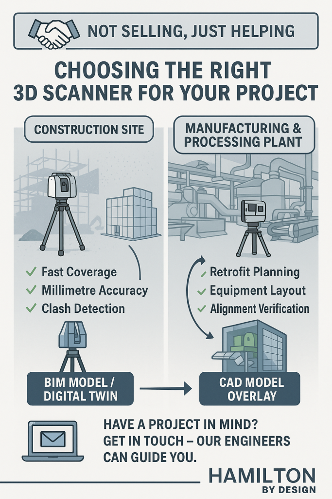
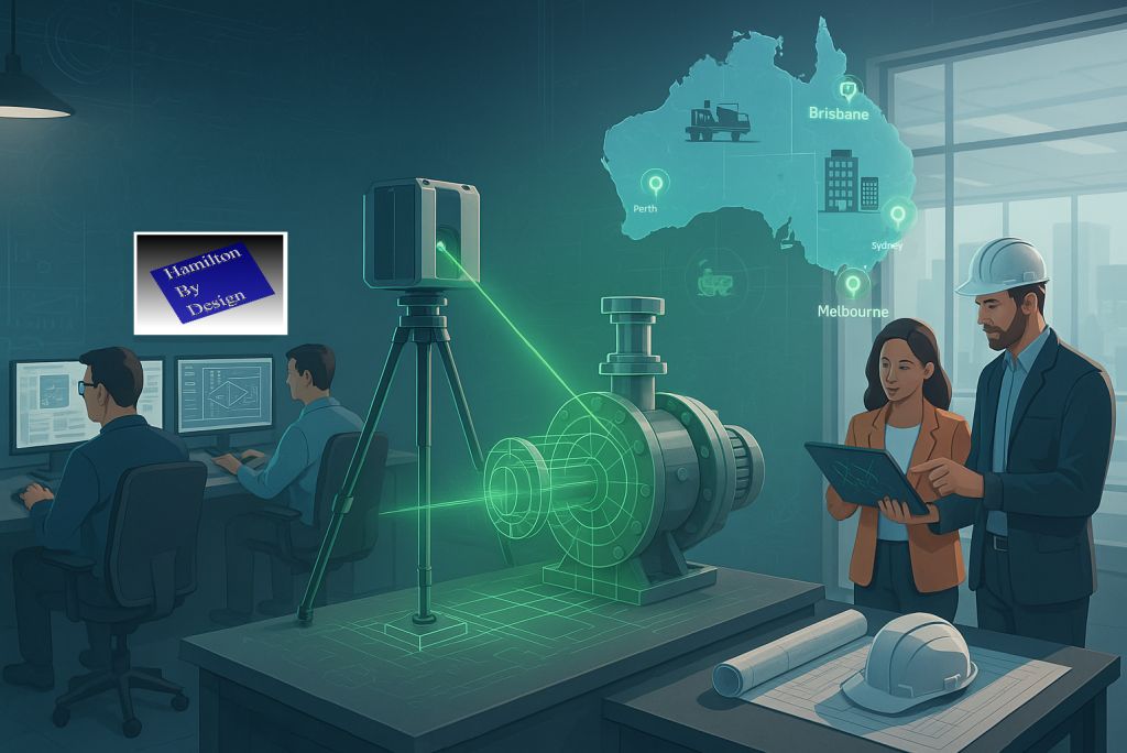
- 3D Scanning (via LiDAR, laser, terrestrial/mobile scanners): captures the existing geometry of structures, equipment, piping, chutes, supports, tanks, etc., as a dense point cloud. Creates a digital “reality capture” of the plant in its current (often messy) state.
- 3D Modelling: turning that data (point clouds, mesh) into clean, usable engineering-geometry — CAD models, as-built / retrofit layouts, clash-detection, wear mapping, digital twins, etc.
The power comes when you integrate the two — when the reality captured in scan form feeds directly into your modelling/design workflows rather than being a separate survey activity that’s then “interpreted” or “assumed.”
Why Combine Scanning + Modelling? Key Benefits
Here are the main advantages you get when you deploy both in an integrated workflow:
| Benefit | What it Means for PMs / Engineering / Plant Ops | Examples / Impacts |
|---|---|---|
| Accuracy & Reality Verification | Verify what’s actually in the plant vs what drawings say. Identify deformations, misalignments, wear, obstructions, or changes that weren’t captured in paper drawings. | Mill liner wear profiles; chute/hopper buildup; misaligned conveyors or supports discovered post-scan. |
| Reduced Risk, Safer Access | Scanning can be done with limited or no shutdown, and from safer vantage points. Less need for personnel to enter hazardous or confined spaces. | Scanning inside crushers, under conveyors, or at height without scaffolding. |
| Time & Cost Savings | Faster surveying; fewer repeat field trips; less rework; fewer surprises during shutdowns or retrofit work. | Scan once, model many; clashes found in model instead of in the field; pre-fabrication of replacement parts. |
| Better Shutdown / Retrofit Planning | Use accurate as-built models so new equipment fits, interferences are caught, installation time is optimized. | New pipelines routed without conflict; steelwork/supports prefabricated; shutdown windows shortened. |
| Maintenance & Asset Lifecycle Management | Scan history becomes a baseline for monitoring wear or deformation. Enables predictive maintenance rather than reactive. | Comparing scans over time to track wear; scheduling relining of chutes; monitoring structural integrity. |
| Improved Decision Making & Visualisation | Engineers, superintendents, planners can visualise the plant as it is — space constraints, access routes, clearances — before making decisions. | Clash-detection between new and existing frames; planning maintenance access; safety audits. |
| Digital Twin / Integration for Future-Ready Plant | Once you have accurate geometric models you can integrate with IoT, process data, simulation tools, condition monitoring etc. | Digital twins that simulate flow, energy use, wear; using scan data to feed CFD or FEA; feeding into operational dashboards. |
Challenges & How to Overcome Them
Of course, there are pitfalls. Ensuring scanning + modelling delivers value requires attention to:
- Planning the scanning campaign (scan positions, control points, resolution) to avoid shadow zones or missing data.
- Choosing hardware and equipment that can operate under plant conditions (dust, vibration, temperature, restricted access).
- Processing & registration of point clouds, managing the large data sets, and ensuring clean, usable models.
- Ensuring modelling workflow aligns with engineering design tools (CAD systems, formats, tolerances) so that the scan data is usable without excessive cleanup.
- Maintaining the model: when plant layouts or equipment change, keeping the scan or model up to date so your decisions are based on recent reality.
At Hamilton By Design we emphasise these aspects; our scan-to-CAD workflows are built to align with plant engineering needs, and we help clients plan and manage the full lifecycle.
Real World Applications in Mining & Process Plants
Here’s how combined scanning + modelling is applied (and what you might look for in your own facility):
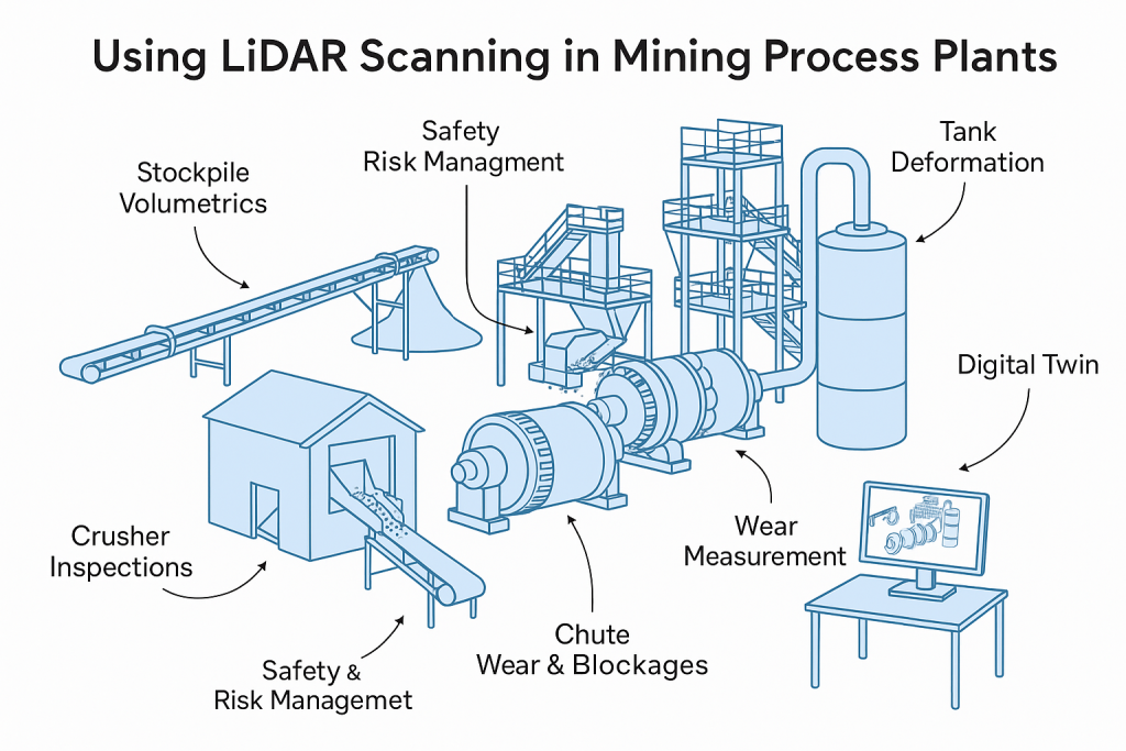
- Wear & Relining: scanning mill, crusher liners, chutes or hoppers to model wear profiles; predict failures; design replacement parts that fit exactly.
- Retrofits & Expansions: mapping existing steel, pipe racks, conveyors, etc., creating accurate “as built” model, checking for clashes, optimizing layouts, prefabricating supports.
- Stockpile / Volumetric Monitoring: using scans or LiDAR to measure stockpile volumes for planning and reporting; integrating with models to monitor material movement and flow.
- Safety & Clearance Checking: verifying that walkways, egress paths, platforms have maintained their clearances; assess structural changes; check for deformation or damage.
- Shutdown Planning: using accurate 3D models to plan the scope, access, scaffold/frame erection, pipe removal etc., so shutdown time is minimised.
Why Choose Hamilton By Design
To get full value from the scan + model combination, you need more than just “we’ll scan it” or “we’ll make a model” — you need a partner who understands both the field realities and the engineering rigour. Here’s where Hamilton By Design excels:
- Strong engineering experience in mining & processing plant settings, so we know what level of detail, what tolerances, and what access constraints matter.
- Proven tools & workflows: from LiDAR / laser scanner work that captures site conditions even under harsh conditions, to solid CAD modelling/reporting that aligns with your fabrication/installation requirements.
- Scan-to-CAD workflows: not just raw point clouds, but models that feed directly into design, maintenance, procurement and operations.
- Focus on accuracy, safety, and reduced downtime: ensuring that field work, design, installation etc., are as efficient and risk-averse as possible.
- Use of modern digital techniques (digital twins, clash detection etc.) so that data isn’t just stored, but actively used to drive improvements.
Practical Steps to Get Started / Best Practice Tips
If you’re managing a plant or engineering project, here are some steps to adopt scanning + modelling optimally:
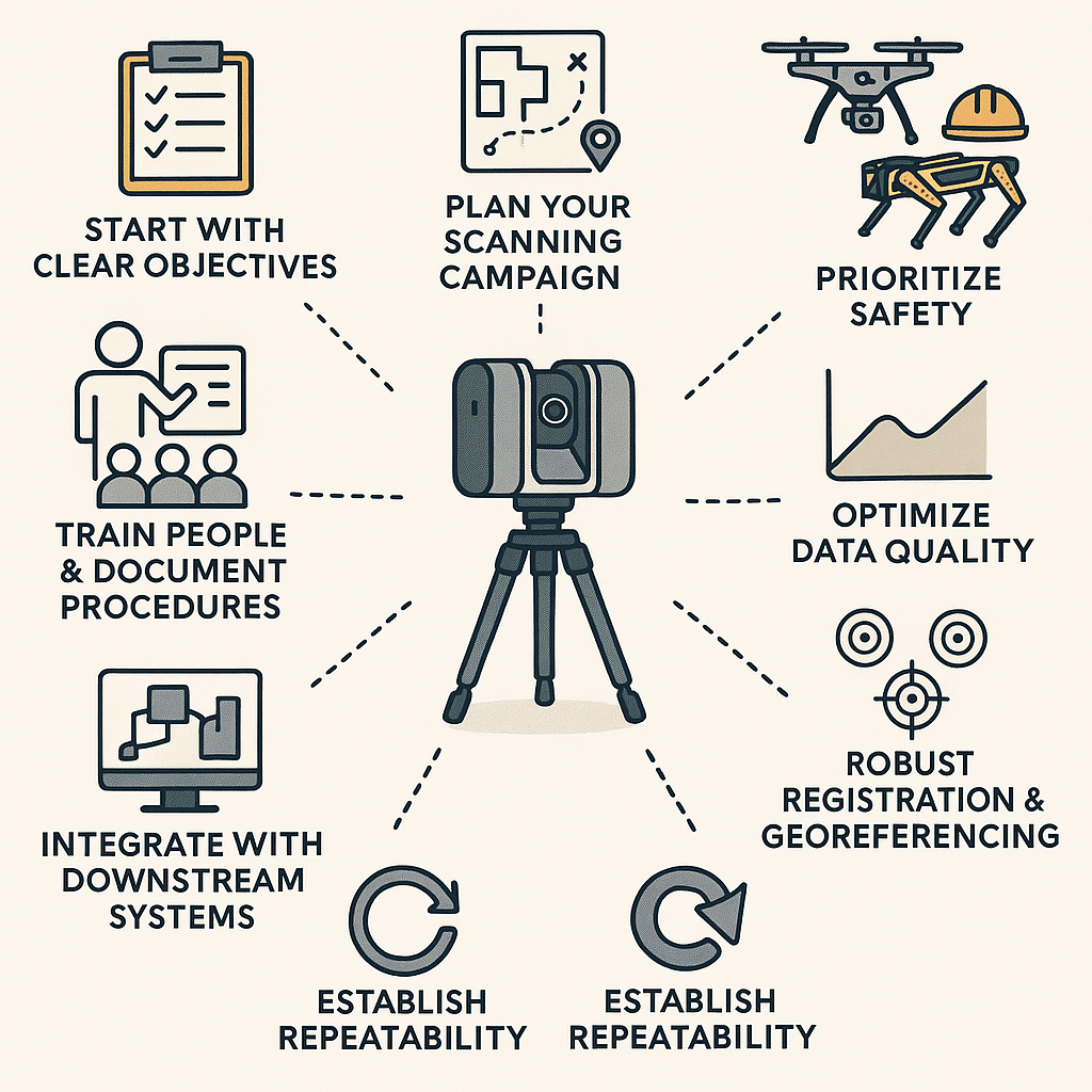
- Define Clear Objectives: What do you want from this scan + model? Wear profiles, retrofit, layout changes, safety audit etc.
- Survey Planning: Decide scan positions, control points, resolution (density) based on the objectives and site constraints. Consider access, safety, shutdown windows.
- Use Appropriate Hardware: Choose scanners suited to environment (dust, heat), also ensure regulatory and IP protection etc.
- Data Processing & Modelling Tools: Have the capacity/software to register, clean, mesh or extract CAD geometry.
- Integrate into Existing Engineering Processes: Ensure the outputs are compatible with your CAD standards, procurement, installation etc.
- Iterate & Maintain: Frequent scans over time to track changes; update models when plant changes; feed maintenance, design and operations with new data.
Conclusion
In mining process plants, time, safety, and certainty matter. By combining 3D scanning with sound 3D modelling you don’t just get a snapshot of your plant — you gain a powerful toolset to reduce downtime, avoid rework, improve safety, and enhance decision-making.
If you’re responsible for uptime, capital works, maintenance or process improvements, this integration can reshape how you plan, maintain, and operate. At Hamilton By Design, we’re helping clients in Australia harness this power — turning reality into design confidence, and giving stakeholders peace of mind that the layout, equipment, and safety are aligned not to yesterday’s drawings but to today’s reality.