From the growing commercial hubs of Parramatta and Chatswood to the complex redevelopments across Sydney’s Eastern Suburbs, the construction industry is demanding more accuracy, faster turnaround, and fewer on-site surprises.
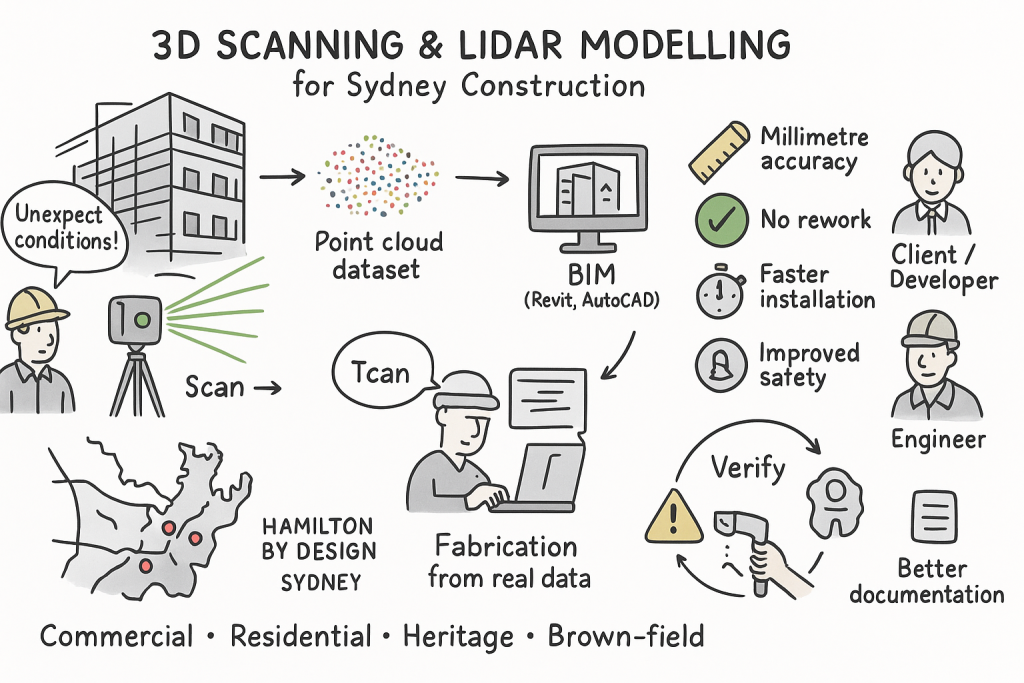
At Hamilton By Design, we use 3D scanning and LiDAR technology to help builders, engineers, and developers capture, model, and verify real site conditions with millimetre accuracy.
Our advanced 3D models ensure every structural, mechanical, or architectural component fits perfectly on site — helping Sydney’s construction professionals deliver projects right the first time.
High-Precision Site Capture with LiDAR Scanning
Using advanced LiDAR (Light Detection and Ranging) technology, our scanners record millions of laser points per second to create a complete 3D “point cloud” of your site or structure.
Whether we’re scanning a commercial building in Chatswood, a multi-level development in Parramatta, or a heritage renovation in Sydney’s Eastern Suburbs, LiDAR scanning allows us to document every detail — without disruption to your workflow.
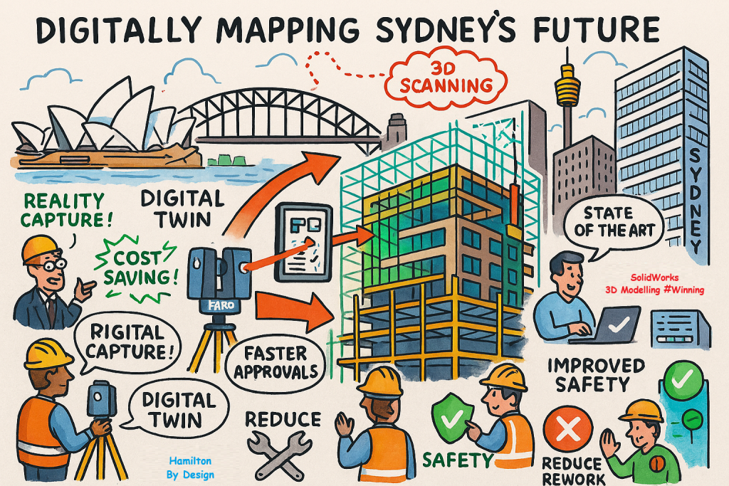
The result is a digital twin of your project site that forms the foundation for precise design, fabrication, and installation.
From Point Cloud to Construction-Ready Model
Once scanning is complete, our engineers convert the LiDAR data into accurate 3D CAD and BIM models that integrate seamlessly into platforms such as Revit, AutoCAD, Navisworks, and SolidWorks.
This digital workflow allows your team to:
Validate as-built conditions before design or fabrication
Identify clashes and alignment issues early
Plan site installations with confidence
Reduce rework and delays during construction
By designing and fabricating to real-world data, Sydney contractors can save valuable time and eliminate unnecessary on-site adjustments.
Why Sydney Contractors Choose 3D Scanning and LiDAR
Millimetre Accuracy: Perfect alignment between fabricated and existing structures.
Reduced Rework: Detect and fix issues before they reach site.
Improved Safety: Non-invasive scanning of hard-to-reach areas.
Faster Installation: Minimise downtime and site delays.
Better Documentation: Maintain accurate records for QA and future maintenance.
Across Chatswood, Parramatta, and Sydney’s Eastern Suburbs, our clients use LiDAR scanning to bring greater certainty to every phase of construction.
Supporting Projects Across Sydney
Hamilton By Design supports a wide range of construction and engineering projects across metropolitan Sydney, including:
Commercial and retail developments in Chatswood and Parramatta
Luxury residential projects and architectural fit-outs in Sydney’s Eastern Suburbs
Industrial and infrastructure upgrades throughout Greater Sydney
Brownfield and refurbishment projects requiring accurate as-built data
Whether it’s a new build or a complex retrofit, we make sure every part of your design fits the first time.
Partner with Hamilton By Design
If you’re managing or planning a construction project in Chatswood, Parramatta, or Sydney’s Eastern Suburbs, Hamilton By Design offers the experience and technology to capture, model, and verify your site with precision.
Our 3D scanning and LiDAR services help Sydney builders, designers, and fabricators deliver more accurate results — reducing risk, rework, and cost.
Sydney’s construction industry is booming — from commercial towers and infrastructure upgrades to industrial developments and complex refurbishments. But as sites become more congested and designs more complex, achieving perfect alignment between fabricated and installed components has never been more challenging.
That’s where 3D scanning and LiDAR technology come in. At Hamilton By Design, we provide high-precision digital capture and 3D modelling services that ensure every element of your construction project fits seamlessly together, saving time, cost, and effort onsite.
Capturing the Real Site with LiDAR Scanning
Using LiDAR (Light Detection and Ranging) scanners, we capture millions of laser measurements per second to create an exact 3D digital record — known as a point cloud — of your construction site or structure.
This means we can document existing conditions, monitor progress, and verify installations with millimetre-level precision. For Sydney builders, engineers, and contractors, that data eliminates the guesswork and drastically reduces costly clashes and rework later on.
From Point Cloud to 3D Model
Once the LiDAR data is captured, it’s processed into detailed 3D CAD and BIM models compatible with leading design software such as Revit, AutoCAD, SolidWorks, and Navisworks.
These accurate models allow design teams to:
Validate and update as-built conditions before fabrication
Detect clashes and misalignments before installation
Plan modifications and extensions with confidence
Coordinate between mechanical, structural, and architectural disciplines
By working from a true digital twin of your Sydney site, you can be sure every part — from prefabricated frames to pipe runs — will fit exactly where it should.
Why Sydney Construction Projects Are Turning to 3D Scanning
Reduced Rework: Identify design and fabrication issues before they reach site.
Improved Safety: Capture high or restricted areas without scaffolding or shutdowns.
Shorter Installation Times: Minimise downtime and delays during fit-up.
Precise Documentation: Maintain accurate records for QA and handover.
Better Collaboration: Integrate real-world data into your BIM environment.
From commercial fit-outs to infrastructure projects across Greater Sydney, 3D scanning provides a single source of truth for every stakeholder.
Typical Sydney Projects Using LiDAR and 3D Modelling
Hamilton By Design supports a range of construction and engineering clients, including:
Commercial and residential developments in the CBD and inner suburbs
Industrial plant upgrades across Western Sydney
Transport and infrastructure projects under NSW Government programs
Refurbishment and brownfield works requiring detailed as-built verification
Each project benefits from faster delivery, greater precision, and stronger communication between designers, builders, and clients.
Partner with Hamilton By Design
If you’re working on a Sydney construction or infrastructure project and need accurate 3D site data, as-built modelling, or fit-up verification, Hamilton By Design can help.
Our experienced mechanical and design specialists combine field scanning with advanced 3D modelling to deliver practical, reliable results that make construction smoother — and smarter.
Meta Description (for SEO): Discover how Hamilton By Design uses 3D scanning, LiDAR technology, and advanced 3D modelling to ensure every part fits perfectly on site. Reduce rework, improve accuracy, and build with confidence.
The Future of Engineering Accuracy
When it comes to engineering, fabrication, and site installation — accuracy is everything. Even a few millimetres out can mean costly rework, delays, and lost time.
At Hamilton By Design, we bring together 3D scanning, LiDAR technology, and precision 3D modelling to capture the real-world geometry of your site and convert it into usable, reliable digital models. The result? Components that fit together seamlessly — first time, every time.
What Is LiDAR 3D Scanning?
LiDAR (Light Detection and Ranging) uses laser light to map physical environments in extraordinary detail. Our scanners capture millions of data points per second, creating a precise digital “point cloud” of your plant, equipment, or structure.
Unlike traditional surveying, LiDAR scanning provides high-resolution, three-dimensional measurements that reflect the exact conditions on site — no assumptions, no approximations.
This allows engineers and designers to work with accurate as-built data, reducing the risk of design clashes and installation errors.
From Scan to Model: Turning Data Into Design Confidence
After scanning, Hamilton By Design processes the LiDAR data into intelligent 3D CAD models. These models can be imported into major design platforms such as AutoCAD, SolidWorks, Revit, and Plant3D — ensuring complete compatibility with your existing workflows.
Our experienced mechanical designers use this data to:
Validate and verify existing plant layouts
Model new mechanical components and assemblies
Check alignment and clash detection before fabrication
Create fabrication-ready models and installation drawings
This digital workflow ensures every piece — from piping spools to structural frames — fits perfectly when installed on site.
The Benefits of 3D Scanning and LiDAR Modelling
✅ Unmatched Accuracy: Sub-millimetre precision that eliminates rework. ✅ Time Efficiency: Rapid data capture across complex or hard-to-access areas. ✅ Improved Safety: Remote scanning reduces time spent in high-risk environments. ✅ Reduced Downtime: Capture plant data without interrupting operations. ✅ Seamless Integration: Easily merge mechanical, structural, and piping models.
Applications Across Industries
Our 3D scanning and LiDAR services support projects in:
Mining and mineral processing
Oil, gas, and energy facilities
Water and wastewater plants
Manufacturing and industrial upgrades
Brownfield and retrofit projects
No matter the scale or complexity, accurate digital capture means faster delivery and fewer surprises once the project reaches site.
Real-World Results
Clients who incorporate 3D scanning into their project planning often report:
Up to 50% reduction in on-site rework
Shorter installation times
Improved cross-discipline collaboration
Higher fabrication quality
By identifying spatial conflicts before fabrication, Hamilton By Design helps ensure your project runs smoother — saving both time and money.
Talk to Hamilton By Design
If your next project involves tight tolerances, plant upgrades, or complex mechanical fit-ups, our 3D scanning and modelling team can help.
In mining and mineral processing environments, small mis-fits, outdated drawings, or inaccurate assumptions can translate into shutdowns, costly rework, or worse, safety incidents. For PMs, superintendents, engineering managers and plants operating under heavy uptime and safety constraints, combining 3D scanning and 3D modelling isn’t just “nice to have” — it’s becoming essential. At Hamilton By Design, we’ve leveraged this combination to deliver greater predictability, lower cost, and improved safety across multiple projects.
What are 3D Scanning and 3D Modelling?
3D Scanning (via LiDAR, laser, terrestrial/mobile scanners): captures the existing geometry of structures, equipment, piping, chutes, supports, tanks, etc., as a dense point cloud. Creates a digital “reality capture” of the plant in its current (often messy) state.
3D Modelling: turning that data (point clouds, mesh) into clean, usable engineering-geometry — CAD models, as-built / retrofit layouts, clash-detection, wear mapping, digital twins, etc.
The power comes when you integrate the two — when the reality captured in scan form feeds directly into your modelling/design workflows rather than being a separate survey activity that’s then “interpreted” or “assumed.”
Why Combine Scanning + Modelling? Key Benefits
Here are the main advantages you get when you deploy both in an integrated workflow:
Benefit
What it Means for PMs / Engineering / Plant Ops
Examples / Impacts
Accuracy & Reality Verification
Verify what’s actually in the plant vs what drawings say. Identify deformations, misalignments, wear, obstructions, or changes that weren’t captured in paper drawings.
Scanning can be done with limited or no shutdown, and from safer vantage points. Less need for personnel to enter hazardous or confined spaces.
Scanning inside crushers, under conveyors, or at height without scaffolding.
Time & Cost Savings
Faster surveying; fewer repeat field trips; less rework; fewer surprises during shutdowns or retrofit work.
Scan once, model many; clashes found in model instead of in the field; pre-fabrication of replacement parts.
Better Shutdown / Retrofit Planning
Use accurate as-built models so new equipment fits, interferences are caught, installation time is optimized.
New pipelines routed without conflict; steelwork/supports prefabricated; shutdown windows shortened.
Maintenance & Asset Lifecycle Management
Scan history becomes a baseline for monitoring wear or deformation. Enables predictive maintenance rather than reactive.
Comparing scans over time to track wear; scheduling relining of chutes; monitoring structural integrity.
Improved Decision Making & Visualisation
Engineers, superintendents, planners can visualise the plant as it is — space constraints, access routes, clearances — before making decisions.
Clash-detection between new and existing frames; planning maintenance access; safety audits.
Digital Twin / Integration for Future-Ready Plant
Once you have accurate geometric models you can integrate with IoT, process data, simulation tools, condition monitoring etc.
Digital twins that simulate flow, energy use, wear; using scan data to feed CFD or FEA; feeding into operational dashboards.
Challenges & How to Overcome Them
Of course, there are pitfalls. Ensuring scanning + modelling delivers value requires attention to:
Planning the scanning campaign (scan positions, control points, resolution) to avoid shadow zones or missing data.
Choosing hardware and equipment that can operate under plant conditions (dust, vibration, temperature, restricted access).
Processing & registration of point clouds, managing the large data sets, and ensuring clean, usable models.
Ensuring modelling workflow aligns with engineering design tools (CAD systems, formats, tolerances) so that the scan data is usable without excessive cleanup.
Maintaining the model: when plant layouts or equipment change, keeping the scan or model up to date so your decisions are based on recent reality.
At Hamilton By Design we emphasise these aspects; our scan-to-CAD workflows are built to align with plant engineering needs, and we help clients plan and manage the full lifecycle.
Real World Applications in Mining & Process Plants
Here’s how combined scanning + modelling is applied (and what you might look for in your own facility):
Wear & Relining: scanning mill, crusher liners, chutes or hoppers to model wear profiles; predict failures; design replacement parts that fit exactly.
Stockpile / Volumetric Monitoring: using scans or LiDAR to measure stockpile volumes for planning and reporting; integrating with models to monitor material movement and flow.
Safety & Clearance Checking: verifying that walkways, egress paths, platforms have maintained their clearances; assess structural changes; check for deformation or damage.
Shutdown Planning: using accurate 3D models to plan the scope, access, scaffold/frame erection, pipe removal etc., so shutdown time is minimised.
Why Choose Hamilton By Design
To get full value from the scan + model combination, you need more than just “we’ll scan it” or “we’ll make a model” — you need a partner who understands both the field realities and the engineering rigour. Here’s where Hamilton By Design excels:
Strong engineering experience in mining & processing plant settings, so we know what level of detail, what tolerances, and what access constraints matter.
Proven tools & workflows: from LiDAR / laser scanner work that captures site conditions even under harsh conditions, to solid CAD modelling/reporting that aligns with your fabrication/installation requirements.
Scan-to-CAD workflows: not just raw point clouds, but models that feed directly into design, maintenance, procurement and operations.
Focus on accuracy, safety, and reduced downtime: ensuring that field work, design, installation etc., are as efficient and risk-averse as possible.
Use of modern digital techniques (digital twins, clash detection etc.) so that data isn’t just stored, but actively used to drive improvements.
Practical Steps to Get Started / Best Practice Tips
If you’re managing a plant or engineering project, here are some steps to adopt scanning + modelling optimally:
Define Clear Objectives: What do you want from this scan + model? Wear profiles, retrofit, layout changes, safety audit etc.
Survey Planning: Decide scan positions, control points, resolution (density) based on the objectives and site constraints. Consider access, safety, shutdown windows.
Use Appropriate Hardware: Choose scanners suited to environment (dust, heat), also ensure regulatory and IP protection etc.
Data Processing & Modelling Tools: Have the capacity/software to register, clean, mesh or extract CAD geometry.
Integrate into Existing Engineering Processes: Ensure the outputs are compatible with your CAD standards, procurement, installation etc.
Iterate & Maintain: Frequent scans over time to track changes; update models when plant changes; feed maintenance, design and operations with new data.
Conclusion
In mining process plants, time, safety, and certainty matter. By combining 3D scanning with sound 3D modelling you don’t just get a snapshot of your plant — you gain a powerful toolset to reduce downtime, avoid rework, improve safety, and enhance decision-making.
If you’re responsible for uptime, capital works, maintenance or process improvements, this integration can reshape how you plan, maintain, and operate. At Hamilton By Design, we’re helping clients in Australia harness this power — turning reality into design confidence, and giving stakeholders peace of mind that the layout, equipment, and safety are aligned not to yesterday’s drawings but to today’s reality.
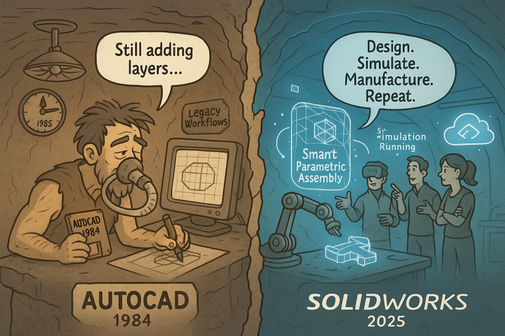
In the 1980s, AutoCAD was revolutionary. It replaced drafting boards and sharpened pencils with a digital drawing tool. Architects, engineers, and designers suddenly had a new way to bring ideas to life — faster, cleaner, and more accurate than ever before.
But here’s the problem: it’s 2025 now, and AutoCAD is still trying to breathe the same thin air it did back then.
Stuck in 2D While the World Moved On
Today’s engineering isn’t about drawing — it’s about designing. It’s about simulating real-world forces, visualizing assemblies, testing tolerances, and producing manufacturable parts before a single prototype is built.
AutoCAD, at its core, is still a 2D drafting platform trying to wear a 3D mask. The workflows are fragmented, the feature set feels patched together, and it lacks the intelligence modern teams demand.
By contrast, SOLIDWORKS was built for this century — fully parametric, model-driven, and collaborative. When you make a change to a design in SOLIDWORKS, every part, drawing, and assembly updates instantly. That’s not an upgrade; that’s evolution.
Design Needs Intelligence, Not Layers
AutoCAD still asks you to think in layers and lines — the language of draftsmen. SOLIDWORKS speaks the language of relationships, assemblies, and constraints — the language of engineers and innovators.
Modern design tools must integrate simulation, visualization, and manufacturability. They must predict behavior, test fit, and optimize before production. AutoCAD just can’t breathe in that environment anymore — it’s stuck flipping between tabs while SOLIDWORKS users are already printing parts.
Collaboration and Data: The New Oxygen
The world doesn’t design in isolation anymore. Teams are global, deadlines are tighter, and innovation cycles are shorter. AutoCAD’s file-based approach is like passing blueprints across a fax machine.
SOLIDWORKS integrates cloud data management, real-time collaboration, and digital twin technology — letting design teams iterate and innovate in real time, anywhere in the world.
The Future Is 3D — and It’s Already Here
You wouldn’t build an electric vehicle using a typewriter. So why design modern products with 1980s software?
SOLIDWORKS represents the present and the future — intelligent modeling, simulation-driven design, and integrated manufacturing tools that push boundaries instead of tracing them.
Final Thoughts
AutoCAD made history — no one can deny that. But history belongs in the museum, not the manufacturing floor.
If your software is still gasping for air in a 2D world, maybe it’s time to give it a well-earned retirement. SOLIDWORKS doesn’t imitate innovation — it defines it.
Mechanical engineering has always been a balance between creativity and certainty. Every bracket, frame, chute, or structural support we design must perform under real loads, temperatures, and conditions — often in environments where failure simply isn’t an option.
That’s where Finite Element Analysis (FEA) earns its place as one of the most powerful tools in modern design. It allows engineers to move from assumption to verification — transforming the way we predict, test, and optimise mechanical systems.
What Is FEA — and Why It Matters
FEA divides complex geometry into a network of small, interconnected elements. By solving the physical equations that govern stress, strain, and displacement across those elements, engineers can predict how a structure behaves under load, vibration, or temperature.
Instead of relying solely on hand calculations or over-built safety factors, FEA provides quantitative insight into performance — letting us see where structures flex, where stress concentrates, and how design choices affect real-world outcomes.
In mechanical engineering, that means fewer prototypes, lower material costs, and far greater design confidence.
1. Static Analysis — The Foundation of Structural Validation
Static linear analysis is the foundation of most FEA work. It evaluates how a structure responds to steady, time-independent loads such as gravity, pressure, or fixed equipment weight.
Through static analysis, engineers can:
Visualise stress and displacement distribution across a part or assembly.
Evaluate safety factors under different loading conditions.
Check stiffness and material utilisation before fabrication.
Identify weak points or stress concentrations early in design.
This baseline validation is the difference between a design that “should” work and one that will.
2. Assembly-Level Simulation — Seeing the Whole System
Few machines fail because a single part breaks. Most failures happen when components interact under load — bolts shear, brackets twist, or welds experience unplanned tension.
FEA allows engineers to simulate entire assemblies, including:
Contact between parts (bonded, sliding, or frictional).
Realistic boundary conditions such as bearings, springs, or pinned joints.
The influence of welds, fasteners, or gaskets on overall performance.
This system-level view helps mechanical engineers design not only for strength, but also for compatibility and reliability across the full structure.
3. Mesh Control — Accuracy Where It Counts
A simulation is only as good as its mesh. By controlling element size and density, engineers can capture critical detail in stress-sensitive regions like fillets, bolt holes, and weld toes.
Modern FEA tools use adaptive meshing — refining the model automatically in areas of high stress until the solution converges. That means precise, efficient results without excessive computation time.
4. Thermal-Structural Interaction — When Heat Becomes a Load
Many mechanical systems face thermal as well as mechanical challenges. Whether it’s ducting in a process plant or hoppers near heat sources, temperature gradients can cause expansion, distortion, or thermal stress.
FEA allows engineers to:
Model steady-state or transient heat transfer through solids.
Apply convection, radiation, or temperature boundary conditions.
Combine thermal and structural analyses to study thermal expansion and thermal fatigue.
Understanding how heat and load combine helps ensure equipment remains stable, safe, and accurate throughout its lifecycle.
5. Modal and Buckling Analysis — Designing Against Instability
Some risks are invisible until they’re simulated. Vibration and buckling are two of the most overlooked — yet most common — causes of structural failure.
Modal Analysis
Determines a structure’s natural frequencies and mode shapes, helping designers avoid resonance with operating machinery, fans, or conveyors.
Buckling Analysis
Predicts the critical load at which slender members or thin-walled panels lose stability — allowing engineers to reinforce and optimise designs early.
By identifying these limits before fabrication, engineers can prevent problems that are expensive and dangerous to discover on site.
Design Optimisation — Smarter, Lighter, Stronger
Good design is rarely about adding material; it’s about using it wisely. FEA supports parametric and goal-based optimisation, enabling engineers to vary geometry, thickness, or material and automatically test multiple configurations.
You can set objectives such as:
Minimising weight while maintaining strength.
Reducing deflection under fixed loads.
Optimising gusset or flange size for stiffness.
This process of “digital lightweighting” drives better performance and cost efficiency — especially valuable in industries where both material and downtime are expensive.
7. Communication and Confidence
FEA isn’t only a calculation tool — it’s a communication tool. Colour-coded plots, animations, and automated reports make it easier to explain complex mechanical behaviour to project managers, clients, or certifying bodies.
Clear visuals turn stress distributions and displacement fields into a shared language — helping stakeholders understand why certain design choices are made.
Real-World Applications Across Mechanical Engineering
Application
Type of Analysis
Key Benefit
Chutes & Hoppers
Static + Buckling
Confirm wall thickness and frame design for structural load and vibration
Conveyor Frames
Modal + Static
Avoid resonance and ensure adequate stiffness
Pressure Equipment
Thermal + Static
Evaluate thermal stress and hoop stress under load
Machine Brackets
Static + Optimisation
Reduce weight while maintaining rigidity
Platforms & Guarding
Buckling
Validate stability under safety loading
Welded Frames & Supports
Static
Check deformation, stress, and weld performance
These examples show how FEA becomes an everyday design partner — embedded in the workflow of mechanical engineers across manufacturing, resources, and infrastructure.
The Engineer’s Advantage: Data Over Assumption
In traditional design, engineers often relied on prototypes and conservative safety factors. Today, simulation delivers the same assurance — without the waste.
By applying FEA early in the design cycle, mechanical engineers can:
Predict failure modes before they occur.
Shorten development time.
Reduce material usage.
Justify design decisions with quantitative proof.
FEA enables engineers to focus less on guesswork and more on innovation — designing structures that are both efficient and dependable.
Engineering Integrity in Practice
At Hamilton By Design, we integrate FEA into every stage of mechanical design and development. It’s how we ensure that every frame, chute, and mechanical system we deliver performs as intended — safely, efficiently, and reliably.
We use FEA not just to find the limits of materials, but to push the boundaries of design quality — delivering engineering solutions that last in the toughest industrial environments.
Design backed by data isn’t a slogan — it’s how we engineer confidence.
Building a Culture of Verified Design
When FEA becomes part of everyday engineering culture, it changes how teams think. Designers begin to see structures not just as drawings, but as living systems under real forces.
That shift builds trust — between engineer and client, between concept and reality. It’s what defines the future of mechanical design: informed, optimised, and proven before the first bolt is tightened.