In today’s world, accuracy and efficiency can make or break a project. Whether you’re working in architecture, construction, engineering, or product design, you need reliable data — and you need it fast. That’s where 3D point clouds come in.
But there’s an important catch: not all scans are created equal. The difference between an average scan and a great one often comes down to the person behind the scanner. Having someone who understands 3D modeling take the scans can dramatically improve your project’s accuracy, reliability, and overall success.
Let’s break down why.
The Power of 3D Point Clouds
Point clouds are essentially millions of tiny data points that capture the shape of an object, room, or entire site. Together, they create a highly detailed digital snapshot of the real world.
Here’s why this matters:
Precision you can trust – Point clouds deliver incredibly detailed measurements, capturing even the smallest curves and angles.
Nothing gets missed – Multiple scan angles ensure a full, 360° view of your site or object.
Speed and efficiency – What used to take hours (or days) with manual measurements can be captured in minutes.
Built-in context – You’re not just getting numbers; you’re getting a complete digital environment to work inside.
Future-proof data – Once you have a scan, you have a permanent record of your space, ready to use months or years later.
From clash detection to as-built verification, point clouds save time, reduce errors, and make collaboration across teams smoother than ever.
Why the Person Taking the Scan Matters
While technology is powerful, experience is what makes the results reliable. Having a skilled 3D modeler operate the scanner can be the difference between a good project and a great one.
Here’s why an expert makes all the difference:
They know what matters – A modeler understands which details are critical for your project and ensures they’re captured.
Fewer gaps, fewer surprises – Experienced pros know how to plan scan positions to cover every angle and avoid blind spots.
Cleaner, more accurate data – They reduce common issues like noise, misalignment, or missing sections that can throw off your model.
Time saved, headaches avoided – No one wants to redo a scan halfway through a project. A professional ensures you get it right the first time.
Confidence from start to finish – When you know your model is accurate, you can move forward with design and construction decisions without second-guessing.
In short: a great scanner operator doesn’t just deliver data — they deliver peace of mind.
The Bottom Line
3D point clouds are already transforming how projects are planned and delivered. But pairing them with an experienced 3D modeler takes things to the next level.
You’ll get better data, faster turnarounds, and a far lower risk of costly mistakes. And when your goal is to deliver projects on time, on budget, and with zero surprises, that’s an edge you can’t afford to miss.
In the mining industry, system uptime isn’t just a goal—it’s a necessity. Transfer points such as chutes, hoppers, and conveyors are often the most failure-prone components in processing plants, especially in high-wear environments like HPGR (High Pressure Grinding Rolls) circuits. Abrasive ores, heavy impact, fines accumulation, and moisture can all combine to reduce flow efficiency, damage components, and drive up maintenance costs.
At Hamilton By Design, we help mining clients minimise downtime and extend the life of their material handling systems by applying advanced 3D scanning, DEM simulation, smart material selection, and modular design strategies. This ensures that transfer points operate at peak efficiency—day in, day out.
Here’s how we do it:
Optimised Flow with DEM-Based Chute & Hopper Design
Flow blockages and misaligned velocities are among the biggest contributors to transfer point failure in the mining industry. That’s why we use Discrete Element Method (DEM) simulations to model bulk material flow through chutes, hoppers, and transfer transitions.
Through DEM, we can simulate how different ores—ranging from dry coarse rock to sticky fines—move, compact, and impact structures. This allows us to tailor chute geometry, outlet angles, and flow paths in advance, helping:
Prevent material buildup or arching inside hoppers and chutes
Align material velocity with the conveyor belt speed using hood & spoon or trumpet-shaped designs
Reduce wear by managing trajectory and impact points
Not all wear is the same—and neither are the materials we use to combat it. By studying the abrasion and impact zones in your chute and hopper systems, we strategically apply wear liners suited to each application.
Our engineering team selects from:
AR (Abrasion-Resistant) steels for high-wear areas
Ceramic liners in fines-rich or ultra-abrasive streams
Rubber liners to absorb shock and reduce noise
This approach reduces liner replacement frequency, improves operational safety, and lowers the risk of unplanned shutdowns at key transfer points.
3. Dust and Spillage Control: Cleaner, Safer Operation
Dust and spillage around conveyors and transfer chutes can lead to extensive cleanup time, increased maintenance, and health hazards. At Hamilton By Design, we treat this as a core design challenge.
We design chutes and hoppers with:
Tight flange seals at interface points
Enclosed transitions that contain dust at the source
Controlled discharge points to reduce turbulent material drops
This reduces environmental risk and contributes to more consistent plant performance—especially in confined or enclosed processing facilities in the mining industry.
4. Modular & Accessible Designs for Faster Maintenance
When liners or components need replacement, every minute counts. That’s why our chute and hopper systems are built with modular sections—each engineered for fast removal and reinstallation.
Key maintenance-driven design features include:
Bolt-on panels or slide-in liner segments
Accessible inspection doors for safe visual checks
Lightweight modular components for easy handling
These details reduce labour time, enhance safety, and keep your plant online longer—especially critical in HPGR zones where throughput is non-stop.
5. Precision 3D Scanning & 3D Modelling for Retrofit Accuracy
One of the most powerful tools we use is 3D scanning. In retrofit or brownfield projects, physical measurements can be inaccurate or outdated. We solve this by conducting detailed laser scans that generate accurate point cloud data—a precise digital twin of your plant environment.
That data is then transformed into clean 3D CAD models, which we use to:
Design retrofits that precisely match existing structure
Identify interferences or fit-up clashes before fabrication
Reduce install time by ensuring right-first-time fits
This scan-to-CAD workflow dramatically reduces rework and error margins during installation, saving time and cost during shutdown windows.
Real-World Application: HPGR & Minerals Transfer Systems
In HPGR-based circuits, transfer points between crushers, screens, and conveyors experience high rates of wear, dust generation, and blockages—particularly where moisture-rich fines are present.
Here’s how Hamilton By Design’s methodology addresses these pain points:
DEM-based flow modelling ensures the HPGR discharge flows cleanly into chutes and onto conveyors without buildup.
Hood/spoon geometries help track material to belt velocity—minimising belt wear and reducing misalignment.
Strategic liner selection extends life in critical wear zones under extreme abrasion.
Modular chute designs allow for fast liner swap-outs without major disassembly.
3D scanning & CAD design ensures new chute sections fit seamlessly into existing HPGR and conveyor frameworks.
By designing smarter transfer systems with these technologies, we enable operators to reduce downtime, increase liner life, and protect critical assets in high-throughput mining applications.
Faster maintenance turnarounds during scheduled shutdowns
3D scanning & CAD integration
Precise fit, reduced installation time, fewer errors during retrofit
Final Word: Engineering That Keeps the Mining Industry Moving
At Hamilton By Design, we combine mechanical engineering expertise with 3D modelling, material flow simulation, and smart fabrication practices to deliver high-performance chute, hopper, and transfer point systems tailored for the mining industry.
Whether you’re dealing with a problematic HPGR discharge, spillage issues, or planning a brownfield upgrade, our integrated design process delivers results that improve reliability, extend service life, and protect uptime where it matters most.
Looking to retrofit or upgrade transfer systems at your site? Let’s talk. We bring together 3D scanning, DEM modelling, practical engineering, and proven reliability to deliver systems that work—from concept through to install.
Operation, Design Challenges, and the Role of Direct Drive Units In the highly demanding and regulated world of underground coal mining, the reliable and efficient transport of coal from the mining face to the surface is critical. Among the many systems involved in this process, conveyor drives play a pivotal role. These systems are tasked with powering conveyor belts that haul coal over long distances through often confined and hazardous environments. A vital part of this setup includes the use of direct drive units (DDUs), particularly in low-profile applications such as underground operations.
This document explores the functionality of conveyor drives in underground coal mines, the unique challenges faced in their operation, the complexities design engineers encounter in their development, and the concept of the phase “outbye”—a term widely used in underground mining to describe the direction and location of operations.
Conveyor Drives in Underground Coal Mining
A conveyor drive is a mechanical system that powers conveyor belts used to transport materials, in this case, coal. In underground mines, these conveyor belts often run for several kilometers, extending from the coal face (the area where coal is actively being cut and mined) to the shaft or drift that brings the coal to the surface.
The drive systems can be located at several points along the belt:
Head drive: Located at the discharge end of the conveyor.
Tail drive: Located at the loading end.
Mid-belt drives: Installed partway along long conveyors to help manage torque and reduce belt tension.
In the context of underground coal mines, the term “conveyor drive” is generally associated with the head or tail drive unit, which powers the movement of the belt.
Role of Direct Drive Units (DDUs)
Direct Drive Units are electric motors directly coupled to the drive shaft of the conveyor pulley, eliminating the need for intermediary gearboxes or belt drives. These units are especially advantageous in underground mining due to their compact design, reliability, and reduced maintenance.
Benefits of DDUs in Underground Coal Mines
Compact Size: Ideal for low-profile mining applications where vertical space is restricted.
Energy Efficiency: With fewer mechanical components, DDUs offer less friction and mechanical losses.
Lower Maintenance: No gearboxes or belt couplings to service.
Increased Reliability: Fewer parts mean fewer failure points.
Improved Safety: The enclosed design minimizes exposure to moving parts and flammable materials.
Operational Challenges of Conveyor Drives Underground
Underground coal mining presents a set of challenges not commonly encountered in surface operations. Conveyor drives, as the lifeblood of coal transportation, are central to these operational difficulties.
1. Space Constraints
Underground roadways are typically narrow and low, especially in coal seams with minimal thickness. This limitation forces the use of low-profile conveyor systems, which in turn limits the size and configuration of the drive units.
2. Dust and Moisture Exposure
Coal dust is highly abrasive and, in certain concentrations, explosive. Moisture from groundwater or the mining process further complicates the reliability of drive components. Ensuring DDUs are properly sealed and rated for these harsh conditions is critical.
3. Heat and Ventilation
Electric motors generate heat, which must be dissipated. However, underground mines have limited ventilation. Overheating can be a major issue, requiring cooling systems or specialized motor enclosures.
4. Explosion-Proof Requirements
Due to the potential presence of methane gas and coal dust, all electrical equipment, including conveyor drives, must comply with stringent explosion-proof standards (e.g., IECEx or ATEX ratings).
5. Long Haul Distances
Modern coal faces can be several kilometers from the shaft bottom. Transporting coal over long distances places mechanical stress on conveyor belts and drive units, increasing the risk of failure if not properly engineered.
6. Maintenance Access
Accessing conveyor drives for inspection or maintenance can be difficult in tight underground environments. Failures that require replacement or repair can cause significant production delays.
7. Load Variability
The volume of coal being hauled can vary significantly during a shift, which places variable demands on the drive system. The control systems must be able to accommodate fluctuating loads without mechanical strain.
Engineering and Design Challenges
Design engineers are tasked with creating conveyor drive systems that are not only robust and efficient but also compact and compliant with mining regulations. Some of the key design challenges include:
1. System Integration in Confined Spaces
Engineering a system that fits into limited space while delivering the necessary power is a fundamental challenge. Direct drive units help address this by eliminating gearboxes, but the motor itself must still be sized correctly.
2. Material Selection
Materials used must be corrosion-resistant, non-sparking, and capable of withstanding vibration, dust ingress, and moisture. This often limits design options and increases costs.
3. Thermal Management
Ensuring that the drive units do not overheat requires careful thermal modeling and the use of heat-resistant components. In some cases, passive or active cooling systems are integrated.
4. Compliance with Standards
Designs must adhere to a host of mining and electrical standards for flameproof and intrinsically safe equipment. Certification processes can be lengthy and expensive.
5. Modularity and Transportability
Since access to underground sites is limited, equipment must be modular or transportable in pieces small enough to be moved through shafts or drifts. Assembling and commissioning underground adds another layer of complexity.
6. System Control and Monitoring
Advanced drives require smart control systems that can adjust to load demands, monitor for faults, and integrate with mine-wide automation systems. Designing these systems requires interdisciplinary expertise.
7. Redundancy and Reliability Engineering
System failure underground can halt production and pose safety risks. Engineers must design for redundancy and easy switch-over between drive systems when necessary.
Understanding the Term “Outbye”
In underground mining terminology, directionality is essential for communication and logistics. The terms “inbye” and “outbye” are commonly used to describe relative directions underground.
What Does “Outbye” Mean?
Outbye refers to the direction away from the coal face and toward the surface or the mine entrance.
Conversely, inbye means toward the coal face.
For example:
If a miner is walking from the coal face toward the conveyor belt transfer station, they are walking outbye.
If a service vehicle is heading toward the longwall face, it is moving inbye.
Relevance of “Outbye” in Conveyor Systems
In conveyor operations:
The coal face is the inbye starting point.
The belt head drive and transfer points to the main conveyor system are located outbye.
Maintenance and service activities often take place outbye to avoid interfering with production at the face.
Understanding this term is critical for coordinating activities underground, as directions are often communicated using inbye and outbye references rather than compass points or distances.
Innovations and Future Trends
The mining industry continues to evolve, and conveyor drive systems are no exception. Some of the emerging trends and technologies include:
1. Variable Speed Drives (VSDs)
VSDs allow precise control over motor speed and torque, improving efficiency and reducing mechanical stress. They are increasingly paired with direct drive units to optimize performance.
2. Condition Monitoring
Sensors embedded in motors and drive systems can provide real-time feedback on vibration, temperature, and load. Predictive maintenance models reduce downtime.
3. Permanent Magnet Motors
These motors offer higher efficiency and torque density compared to traditional induction motors, making them well-suited for space-constrained environments.
4. Automation and Remote Control
Fully integrated systems that allow operators to monitor and control conveyor drives from surface control rooms are becoming standard.
5. Modular, Plug-and-Play Designs
Future drive units are being designed with ease of installation and replacement in mind, enabling faster deployment and lower maintenance impact.
Conclusion
Conveyor drive systems in underground coal mining are vital to the continuous flow of material and, by extension, the productivity of the entire mining operation. The adoption of direct drive units is helping to meet the unique demands of underground environments by providing compact, reliable, and efficient power transmission solutions.
However, these systems are not without their challenges. From the operational constraints of underground environments to the rigorous demands placed on design engineers, the development and maintenance of these systems require specialized knowledge, innovative thinking, and strict adherence to safety standards.
Moreover, understanding mining-specific terminology such as “outbye” provides important context for the deployment and maintenance of conveyor systems. As technology continues to advance, we can expect to see more intelligent, adaptive, and efficient conveyor drive systems that are better suited to the evolving demands of underground coal mining.
There are two things we’ve always believed at Hamilton By Design:
Accuracy matters.
If you can model it before you make it, do it.
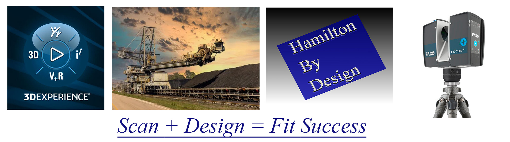
That’s why when the FARO Focus S70 hit the scene in 2017, we were early to the party — not just because it was shiny and new (though it was), but because we knew it would change how we support our clients in mining, processing, and manufacturing environments.
The S70 didn’t just give us a tool — it gave us a superpower: the ability to see an entire site, down to the bolt heads and pipe supports, in full 3D before anyone picked up a wrench. Dust, heat, poor lighting — no problem. With its IP54 rating and extended temperature range, this scanner thrives where other tools tap out.
And we’ve been putting it to work ever since.
“Measure Twice, Cut Once” Just Got a Whole Lot More Real
Laser scanning means we no longer rely on outdated drawings, forgotten markups, or that sketch someone did on the back of a clipboard in 2004.
We’re capturing site geometry down to millimetres, mapping full plant rooms, structural steel, conveyors, tanks, ducts — you name it. And the moment we leave site, we’ve already got the data we need, registered and ready to drop into SolidWorks.
Which, by the way, we’ve been using since 2001.
Yes — long before CAD was cool, we were deep into SolidWorks building models, simulating loads, tweaking fit-ups, and designing smarter mechanical solutions for complex environments. It’s the other half of the story — scan it, then model it, all in-house, all under one roof.
Safety by Design – Literally
Here’s the part people often overlook: 3D laser scanning isn’t just about accuracy — it’s about safety.
We’ve worked across enough plants and mine sites to know that the real hazards are often the things you don’t see in a drawing. Tight access ways. Awkward pipe routing. Obstructions waiting to drop something nasty when a shutdown rolls around.
By scanning and reviewing environments virtually, we can spot those risks early — hazard identification before boots are even on the ground. We help clients:
Reduce time-on-site
Limit the number of field visits
Minimise exposure to high-risk zones
Plan safer shutdowns and installations
That’s a big win in any plant or processing facility — not just for compliance, but for peace of mind.
From Point Cloud to Problem Solved
Since 2017, our scanning and modelling workflows have supported:
Brownfield upgrade projects
Reverse engineering of legacy components
Fabrication and installation validation
Creation of digital twins
Asset audits and documentation updates
And when you pair that with 24 years of SolidWorks expertise, you get more than just a pretty point cloud — you get practical, buildable, fit-for-purpose engineering solutions backed by deep industry knowledge.
Thinking about your next project? Let’s make it smarter from the start.
We’ll scan it, model it, and engineer it as we have been doing for decades — with zero guesswork and full confidence.