At Hamilton By Design, we regularly publish articles about engineering workflows, plant upgrades, LiDAR scanning, mechanical design, and industrial infrastructure.
We also contribute to technical discussions and engineering blogs that explore topics such as point cloud modelling, SolidWorks design, pipework detailing, and mining infrastructure upgrades.
This page provides a collection of additional technical reading and external resources related to engineering design and digital engineering workflows.
These articles complement the work we do at Hamilton By Design and may be useful for engineers, project managers, designers, and plant operators involved in industrial and mining infrastructure projects.

Pipework Detailing and SolidWorks Design
One area where modern digital workflows are particularly valuable is pipework detailing and fabrication drawing development.
By combining LiDAR scanning with SolidWorks modelling, engineers can capture the true geometry of existing plant infrastructure and develop accurate pipe spool drawings for fabrication and installation.
The following article explores how laser scanning data can be used to support this workflow:
From Laser Scan to Pipe Spool Drawings – Using SolidWorks and LiDAR Data for Accurate Pipework Design
https://pipeworkdetailing.blogspot.com/2026/03/from-laser-scan-to-pipe-spool-drawings.html
This article discusses how engineering teams can move from capturing plant geometry with LiDAR scanning through to generating pipe spool drawings for fabrication.
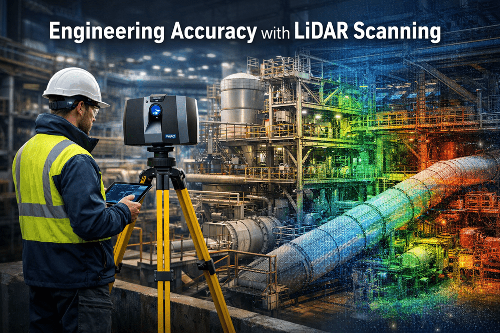
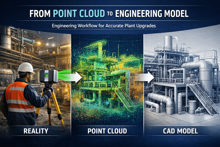
LiDAR Scanning and Engineering Design Workflows
Laser scanning is increasingly used across industrial and mining projects to capture existing plant conditions before upgrades or modifications begin.
At Hamilton By Design we use engineering-grade LiDAR scanning to support:
• Mining infrastructure upgrades
• Industrial plant modifications
• Mechanical equipment installations
• Structural steel design
• Pipework routing and detailing
• Shutdown engineering projects
By converting scan data into engineering models, design teams can work directly against the true geometry of the plant environment.
Related Articles on the Hamilton By Design Website
You may also find the following articles useful:
Engineering Grade 3D Laser Scanning for Mining and Industrial Projects
https://www.hamiltonbydesign.com.au/home/engineering-grade-3d-laser-scanning-mining-industrial/
3D Laser Scanning Across Australia
https://www.hamiltonbydesign.com.au/home/engineering-services/3d-laser-scanning/3d-laser-scanning-across-australia/
3D Laser Scanning for Mining Plant Upgrades
https://www.hamiltonbydesign.com.au/engineering-grade-3d-laser-scanning-mining-plant-upgrades/
3D Laser Scanning for Mining Shutdown Projects
https://www.hamiltonbydesign.com.au/3d-laser-scanning-mining-shutdowns/
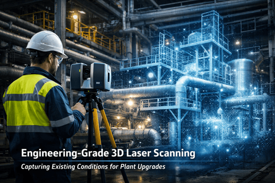
Capture Existing Conditions Before Plant Upgrades
https://www.hamiltonbydesign.com.au/capture-existing-conditions-before-plant-upgrades/
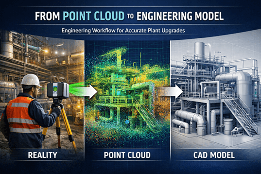
Point Cloud to Engineering Model Workflow
https://www.hamiltonbydesign.com.au/point-cloud-to-engineering-model-workflow/
Why We Share Additional Engineering Reading
Engineering projects often benefit from a combination of practical field knowledge, digital modelling workflows, and collaboration across the engineering community.
By sharing additional articles and resources, we hope to contribute to ongoing discussions about:
• Engineering measurement and accuracy
• Digital engineering workflows
• Mining infrastructure design
• Mechanical and structural modelling
• Industrial plant upgrades
If you are interested in discussing engineering-grade 3D laser scanning, mechanical engineering design, or infrastructure upgrades, please feel free to contact Hamilton By Design.