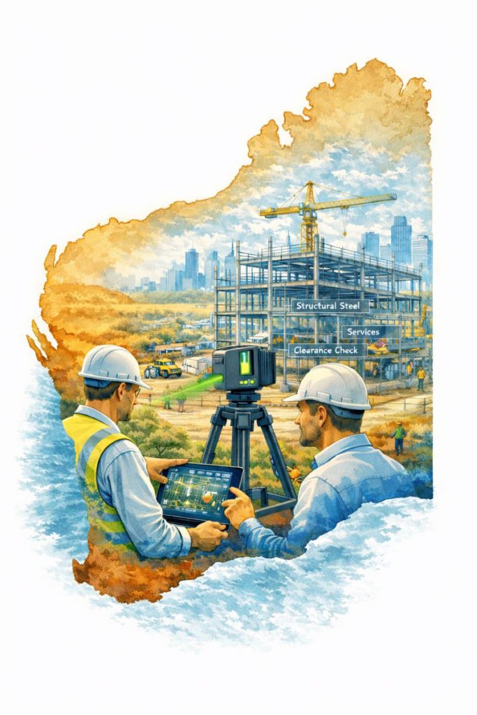
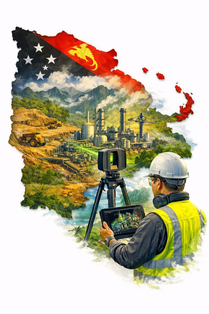
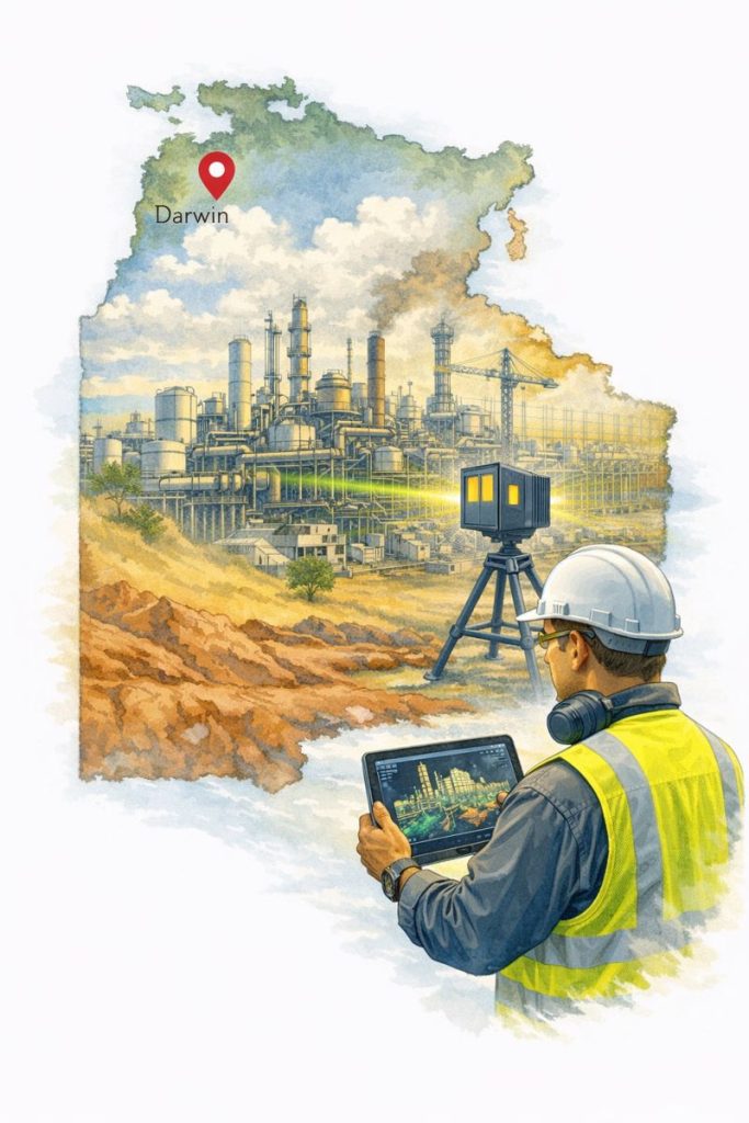
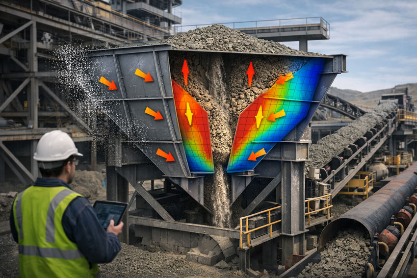
It’s Time to Level Up: Why Mechanical Engineering Consultants Are Key to Unlocking the Power of Point Cloud to 3D Modeling

In today’s competitive manufacturing and fabrication landscape, the difference between success and frustration often comes down to one thing: how well you capture and use data. Traditional methods of measurement, drafting, and design simply can’t keep up with the complexity and pace of modern projects.

Enter point cloud scanning and 3D modeling — a transformative approach that is reshaping how manufacturers, fabricators, and engineers work together. But as powerful as this technology is, getting the most from it takes more than just buying a scanner. It takes expertise, insight, and a partner who can integrate this digital transformation seamlessly into your workflows.

So, is it time to level up and engage mechanical engineering consultants who can make this happen?

We think so — and here’s why.


From Point Cloud to 3D Model: A Game-Changer

When you scan a physical space, component, or assembly using modern laser scanning or photogrammetry, you capture millions of data points — a digital twin of reality. Converting that data into a precise 3D model opens the door to benefits like:

  • Pinpoint Accuracy: Say goodbye to guesswork and human measurement errors.
  • Faster Iteration: Generate manufacturing and fabrication drawings quickly, test design variations digitally, and accelerate your project timelines.
  • Improved Collaboration: Give engineers, fabricators, and stakeholders a single source of truth that everyone can see and work from.
  • Risk Reduction: Spot interferences, clashes, and potential problems before they become costly rework in the shop or on-site.
  • Future-Proofing: Create a digital foundation for maintenance, upgrades, and retrofits years down the line.

This isn’t just better engineering — it’s smarter business.


The Missing Piece: Expertise

Technology alone doesn’t guarantee success. A high-resolution point cloud is just data — and without the right people turning that data into insight, it won’t deliver its full value.

That’s where mechanical engineering consultants come in. By partnering with experts who understand both the technology and the application, you gain:

  • Tailored Workflows: A consultant knows how to align the process with your unique needs, whether it’s structural steel, piping systems, or custom machinery.
  • Best-Practice Modeling: Avoid bloated, unusable models or drawings that don’t reflect fabrication realities.
  • Integrated Solutions: Consultants ensure your 3D models, fabrication drawings, and QA processes work seamlessly with your existing systems.
  • Strategic Insight: Move beyond simply “drawing what’s there” to rethinking processes, improving efficiency, and reducing total cost of ownership.

Why Now Is the Perfect Time

Market pressures are increasing. Labor costs are rising. Margins are under strain. Mistakes are expensive — but digital solutions are more accessible than ever.

Your competitors are already exploring Industry 4.0 technologies like point cloud scanning, 3D modeling, and digital twins. The companies that succeed are the ones that move early, learn fast, and embed these practices into their operations.

Bringing in mechanical engineering consultants allows you to leapfrog the painful trial-and-error phase and start reaping the benefits from day one.


Level Up Your Engineering Today

If you’re still relying on outdated measurement methods, 2D drawings, and siloed workflows, now is the time to level up. Scanning, modeling, and digital collaboration aren’t “nice-to-haves” anymore — they’re the foundation of modern manufacturing and fabrication.

Engage a trusted mechanical engineering consultant who can:

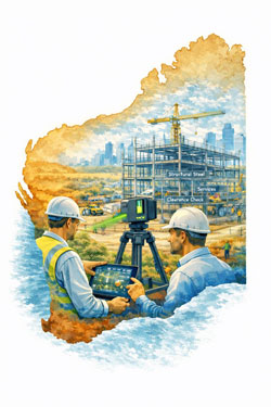
  • Capture your as-built environment accurately
  • Convert point clouds into actionable 3D models
  • Deliver fabrication-ready drawings
  • Help you reduce risk, save time, and improve quality

The future of engineering is here. Don’t just keep up — get ahead.

Consulting Engineers

3D Scanning | Mechanical Engineering | Hamilton By Design

Contact us

Designing for Developing Hazards: Lessons from the Derrimut Crane Collapse

Crane accidents are among the most visible reminders of the risks inherent in construction. The collapse of a crane at a data centre site in Derrimut, Melbourne, brought attention once again to the vulnerability of temporary lifting structures. While formal investigations are still underway, and no conclusions should be drawn prematurely, the event provides a valuable opportunity for reflection within the engineering community.

This article considers the collapse not as an isolated failure but as a case study in hazard identification. In particular, it highlights how mechanical engineers must adapt from a static, design-phase view of risk to a dynamic, real-time approach to hazard monitoring. Wind, soil stability, and load conditions are well-known hazards. But with modern tools — including LiDAR scanning for obstacle detection — engineers can move toward a future where developing hazards are continuously tracked, anticipated, and controlled.


From Hazard Identification to Live Hazard Monitoring

Hazard identification has traditionally been a design-phase process: engineers anticipate risks, apply safety factors, and create conservative margins. This remains essential. Yet the Derrimut collapse illustrates the limits of a static model in a dynamic environment.

Cranes are exposed to evolving hazards:

  • Wind gusts that change minute by minute.
  • Soil stability that shifts with rainfall, excavation, or groundwater.
  • Obstacles such as power lines or nearby structures, which can create cascading risks if struck.
  • Load dynamics, including swinging or sudden movement.

What is needed is a transition from hazard identification to hazard monitoring: a continuous loop where design assumptions are validated against real-time data, and where developing risks are detected before they become failures.


Wind Hazards: Predicting the Unpredictable

Wind is a leading cause of crane collapses. Engineers know the mathematics: pressure rises with the square of velocity. A 50 km/h gust exerts twice the force of a 35 km/h breeze.

Most cranes today are fitted with anemometers and alarms, but these are often basic: a single reading at a single point, with alarms sounding when preset thresholds are exceeded. This approach can miss:

  • Local gust variability along a long jib.
  • Interaction with crane orientation (wind hitting the broadside is more critical than aligned wind).
  • Forecasted conditions that could deteriorate within minutes.

Next-generation wind monitoring could include:

  • Multi-point sensor arrays on cranes.
  • Integration with Bureau of Meteorology gust forecasts.
  • AI models predicting when risk thresholds will be exceeded, not just reporting when they are crossed.
  • Automatic crane repositioning to minimise wind exposure.

This transforms alarms from reactive to predictive — the difference between warning after a hazard is present and anticipating before it materialises.


Soil Hazards: Stability Under Load

Ground conditions are another silent but critical hazard. Outriggers may impose hundreds of kilonewtons on pads, meaning even small soil weaknesses can lead to tilting or overturning.

Engineering practice already includes soil investigations: boreholes, CPT, SPT, and FEA models. But these tests capture conditions before installation, not necessarily during operation. Soil strength can change due to rainfall, groundwater shifts, or nearby excavation.

Live soil monitoring can be achieved with:

  • Load cells under mats to track ground reactions.
  • Settlement gauges to detect tilt.
  • Piezometers for pore pressure during rain events.
  • Integrated warnings when ground resistance trends downward.

This approach acknowledges soil as a living hazard that changes daily.


LiDAR and Obstacle Detection: Power Lines and Proximity Hazards

One striking feature of the Derrimut collapse was the crane’s boom striking power lines. Contact with utilities is a recurrent hazard in crane operations worldwide. While operators are trained to maintain exclusion zones, in practice visibility, fatigue, or unexpected boom movement can still lead to contact.

LiDAR scanning offers a solution.

  • How it works: LiDAR (Light Detection and Ranging) emits laser pulses to map surroundings in 3D with centimetre accuracy. Mounted on a crane, it can create a live digital map of nearby obstacles.
  • Application in cranes:
    • Detecting and mapping power lines, buildings, or scaffolding in the lift path.
    • Setting proximity alarms when a boom, hook, or load approaches a defined clearance.
    • Combining with wind data to predict if gusts could push the load into restricted zones.

In aviation, LiDAR and radar-based systems are standard for obstacle detection. In construction, adoption is patchy. Yet the technology exists, is cost-effective, and could dramatically reduce risks of contact with hazards like live power lines.

LiDAR’s strength lies not only in static mapping but in detecting movement — for example, when a suspended load begins to swing toward a power line due to a gust. This is a quintessential developing hazard, one that static design could never fully capture.


Integrated Hazard Dashboards

Wind, soil, and LiDAR obstacle detection all provide valuable data. But their true power lies in integration. Imagine a crane operator’s cabin equipped with a single dashboard displaying:

  • Wind speeds and gust forecasts, colour-coded for risk.
  • Soil reaction forces under each outrigger, with alerts if settlement is trending.
  • LiDAR mapping of nearby structures and power lines, with real-time clearance zones.
  • Predictive risk models showing probability of instability or contact over the next 30 minutes.

This integration mirrors aviation’s cockpit: multiple inputs fused into actionable guidance. For cranes, such systems could shift the operator’s role from reactive decision-maker to proactive risk manager.


AI as a Predictive Partner

Artificial Intelligence has a natural role in hazard monitoring:

  • Sensor fusion: combining wind, soil, and LiDAR inputs into coherent risk profiles.
  • Prediction: learning from past crane incidents to forecast when risks are likely to escalate.
  • Decision support: providing operators with clear options (“safe to continue lift for 20 minutes” / “halt operations — clearance margin < 1m”).

The challenge is balance. AI should not replace human oversight, but augment it. Over-reliance could create new vulnerabilities if operators become complacent. The design challenge is to build AI into systems that support human judgment rather than substitute for it.


Ethics and Engineering Responsibility

The Derrimut collapse underscores the ethical responsibility of mechanical engineers. Hazard identification is not just a design requirement; it is a matter of public safety. The profession has a duty to anticipate, detect, and control risks wherever possible.

The tools now exist to monitor developing hazards — wind sensors, soil gauges, LiDAR scanners, and AI dashboards. If lives and infrastructure can be protected through wider adoption of these tools, then the question becomes one of responsibility: should they be optional, or mandatory?


Open Questions for the Future

  1. Would integrated live monitoring have reduced the risks at Derrimut?
  2. Should all cranes be fitted with LiDAR obstacle detection as standard?
  3. Do we already have enough technology, but lack regulation and enforcement?
  4. What role should AI play in balancing predictive insight with operator autonomy?

Conclusion

The Derrimut incident remains under investigation. No conclusions can be drawn about its specific cause until findings are published. Yet as a case study, it illustrates the broader point that hazards in crane operations are dynamic. Wind, soil, obstacles, and loads evolve minute by minute.

Mechanical engineers have the tools — wind sensors, soil monitors, LiDAR scanners, integrated dashboards, and AI — to detect these developing hazards. The challenge is to move from a culture of static design assumptions to one of continuous hazard monitoring.

The ultimate professional question is this: If aviation can integrate multiple systems to monitor and predict hazards, why can’t construction do the same for cranes? And if we can, how soon will we accept the ethical responsibility to make it standard?


References and Further Reading

  • ISO 4301 / AS 1418 — Crane standards covering stability and wind.
  • ISO 12480-1:2003 — Safe use of cranes; includes environmental hazard monitoring.
  • WorkSafe Victoria Guidance Notes — Crane safety management.
  • Holický & Retief (2017)Probabilistic treatment of wind action in structural design.
  • Nguyen et al. (2020)Real-time monitoring of crane foundation response under variable soil conditions.
  • Liebherr LICCON — Example of integrated load and geometry monitoring.
  • FAA LLWAS — Aviation’s real-time wind shear alert system, model for construction.
  • Recent research in LiDAR obstacle detection (e.g., IEEE Transactions on Intelligent Transportation Systems) — showing LiDAR’s potential in complex environments.

Structural Drafting | Mechanical Drafting | 3D Laser Scanning

Mechanical Engineering

Consulting Engineers

Maximising Uptime at Transfer Points: How Hamilton By Design Optimises Chutes, Hoppers, and Conveyors for the Mining Industry

In the mining industry, system uptime isn’t just a goal—it’s a necessity. Transfer points such as chutes, hoppers, and conveyors are often the most failure-prone components in processing plants, especially in high-wear environments like HPGR (High Pressure Grinding Rolls) circuits. Abrasive ores, heavy impact, fines accumulation, and moisture can all combine to reduce flow efficiency, damage components, and drive up maintenance costs.

At Hamilton By Design, we help mining clients minimise downtime and extend the life of their material handling systems by applying advanced 3D scanning, DEM simulation, smart material selection, and modular design strategies. This ensures that transfer points operate at peak efficiency—day in, day out.

Here’s how we do it:

Optimised Flow with DEM-Based Chute & Hopper Design

Flow blockages and misaligned velocities are among the biggest contributors to transfer point failure in the mining industry. That’s why we use Discrete Element Method (DEM) simulations to model bulk material flow through chutes, hoppers, and transfer transitions.

Through DEM, we can simulate how different ores—ranging from dry coarse rock to sticky fines—move, compact, and impact structures. This allows us to tailor chute geometry, outlet angles, and flow paths in advance, helping:

  • Prevent material buildup or arching inside hoppers and chutes
  • Align material velocity with the conveyor belt speed using hood & spoon or trumpet-shaped designs
  • Reduce wear by managing trajectory and impact points

Optimised flow equals fewer shutdowns, longer equipment life, and better plant throughput.

Wear-Resistant Liners & Material Engineering

Not all wear is the same—and neither are the materials we use to combat it. By studying the abrasion and impact zones in your chute and hopper systems, we strategically apply wear liners suited to each application.

Our engineering team selects from:

  • AR (Abrasion-Resistant) steels for high-wear areas
  • Ceramic liners in fines-rich or ultra-abrasive streams
  • Rubber liners to absorb shock and reduce noise

This approach reduces liner replacement frequency, improves operational safety, and lowers the risk of unplanned shutdowns at key transfer points.

3. Dust and Spillage Control: Cleaner, Safer Operation

Dust and spillage around conveyors and transfer chutes can lead to extensive cleanup time, increased maintenance, and health hazards. At Hamilton By Design, we treat this as a core design challenge.

We design chutes and hoppers with:

  • Tight flange seals at interface points
  • Enclosed transitions that contain dust at the source
  • Controlled discharge points to reduce turbulent material drops

This reduces environmental risk and contributes to more consistent plant performance—especially in confined or enclosed processing facilities in the mining industry.

4. Modular & Accessible Designs for Faster Maintenance

When liners or components need replacement, every minute counts. That’s why our chute and hopper systems are built with modular sections—each engineered for fast removal and reinstallation.

Key maintenance-driven design features include:

  • Bolt-on panels or slide-in liner segments
  • Accessible inspection doors for safe visual checks
  • Lightweight modular components for easy handling

These details reduce labour time, enhance safety, and keep your plant online longer—especially critical in HPGR zones where throughput is non-stop.

5. Precision 3D Scanning & 3D Modelling for Retrofit Accuracy

One of the most powerful tools we use is 3D scanning. In retrofit or brownfield projects, physical measurements can be inaccurate or outdated. We solve this by conducting detailed laser scans that generate accurate point cloud data—a precise digital twin of your plant environment.

That data is then transformed into clean 3D CAD models, which we use to:

  • Design retrofits that precisely match existing structure
  • Identify interferences or fit-up clashes before fabrication
  • Reduce install time by ensuring right-first-time fits

This scan-to-CAD workflow dramatically reduces rework and error margins during installation, saving time and cost during shutdown windows.

Real-World Application: HPGR & Minerals Transfer Systems

In HPGR-based circuits, transfer points between crushers, screens, and conveyors experience high rates of wear, dust generation, and blockages—particularly where moisture-rich fines are present.

Here’s how Hamilton By Design’s methodology addresses these pain points:

  • DEM-based flow modelling ensures the HPGR discharge flows cleanly into chutes and onto conveyors without buildup.
  • Hood/spoon geometries help track material to belt velocity—minimising belt wear and reducing misalignment.
  • Strategic liner selection extends life in critical wear zones under extreme abrasion.
  • Modular chute designs allow for fast liner swap-outs without major disassembly.
  • 3D scanning & CAD design ensures new chute sections fit seamlessly into existing HPGR and conveyor frameworks.

By designing smarter transfer systems with these technologies, we enable operators to reduce downtime, increase liner life, and protect critical assets in high-throughput mining applications.

Uptime Benefits at a Glance

Performance AreaImpact on Mining Operations
Smooth bulk material flowFewer clogs, improved throughput, longer operating cycles
Velocity-matched dischargeLower conveyor belt wear and downtime
Robust wear protectionLonger life, fewer liner replacements
Modular designFaster maintenance turnarounds during scheduled shutdowns
3D scanning & CAD integrationPrecise fit, reduced installation time, fewer errors during retrofit

Final Word: Engineering That Keeps the Mining Industry Moving

At Hamilton By Design, we combine mechanical engineering expertise with 3D modelling, material flow simulation, and smart fabrication practices to deliver high-performance chute, hopper, and transfer point systems tailored for the mining industry.

Whether you’re dealing with a problematic HPGR discharge, spillage issues, or planning a brownfield upgrade, our integrated design process delivers results that improve reliability, extend service life, and protect uptime where it matters most.

Looking to retrofit or upgrade transfer systems at your site?
Let’s talk. We bring together 3D scanning, DEM modelling, practical engineering, and proven reliability to deliver systems that work—from concept through to install.

Reach out at contact@hamiltonbydesign.com.au

#3DScanning #MiningIndustry #Chutes #Hoppers #TransferPoints #3DModelling #MechanicalEngineering #HPGR #PlantUptime #HamiltonByDesign

Structural Drafting | Mechanical Drafting | 3D Laser Scanning

Mechanical Engineering

Harnessing Opportunity in Australia’s $1.2 B Critical Minerals Push

Australia’s Federal Government has announced an A$1.2 billion Critical Minerals Strategic Reserve, backed by a $1 billion top-up to its existing Critical Minerals Facility. With implementation set for the second half of 2026, the Reserve aims to secure critical minerals—lithium, cobalt, nickel, rare earths—through government offtake agreements and strategic stockpiling miningmonthly.com+15anthonyalbanese.com.au+15discoveryalert.com.au+15.

Why It Matters for Mechanical Engineers

This isn’t just political positioning—it’s a major call to action for mechanical engineering consultancies:

  • Scale and diversification of processing sites – More projects will need robust mechanical systems from crushing and conveying to structural and structural integrity assessments, especially for rare earths and heavy metals.
  • Advanced processing technologies – Selective stockpiling and refining of critical minerals will require high-precision mechanical design, wear management, and optimization of machinery performance.
  • Infrastructure and retrofit demand – The Reserve extends the Critical Minerals Facility’s reach to A$5 billion, catalysing greenfield builds and upgrades—areas where Hamilton By Design excels.

Strategic Insights for Hamilton By Design

At Hamilton By Design, our strength lies in supporting projects from feasibility to commissioning, encompassing:

  • Materials handling systems – conveyors, stockpiles, chutes
  • Structural and fatigue engineering – ensuring safety and longevity under harsh industrial conditions
  • Wear and reliability optimisation – extending lifespan and uptime of mechanical assets
  • Digital tools – such as FEA, 3D scanning, and digital twins to enhance design accuracy and project efficiency

This Government-backed industrial growth is a signal for mining contractors and OEMs to engage expert mechanical consultants early—ensuring streamlined, compliant, and future-proofed system integration.


🛠️ How Hamilton By Design Adds Value

What You GetHow It Helps
Proven materials-handling systems designScalable, reliable conveyors and chutes for critical-mineral plants
End-to-end structural assessmentsEnables compliance with WHS, AS/NZS and long-term asset management
Wear analysis & maintenance planningReduces downtime and extends asset lifespan
Integration of digital engineeringImproves commissioning, reduces risk and cost overruns

With major investments planned and a strong industrial trajectory ahead, now is the time for OEMs and mining clients to tap into specialist mechanical consulting support.

Let’s talk about how Hamilton By Design can partner to deliver cutting‑edge materials handling and structural engineering solutions for your next critical minerals project.

Hamilton By Design | Mechanical Drafting | Structural Drafting | 3-D Lidar Scanning

Rigid Body Dynamics vs Transient Structural Analysis in Mining

Why Both Matter in Mechanical and Structural Engineering

In the fast-paced and high-stakes environment of the Australian mining industry, reliable engineering design isn’t just a competitive advantage — it’s a necessity. Across regions like the Pilbara, Kalgoorlie, the Hunter Valley, Bowen Basin, and Mount Isa, mining operations depend on complex mechanical systems that must perform under extreme loads, harsh conditions, and round-the-clock operation.

To ensure safety, reliability, and performance, mining engineers increasingly rely on advanced simulation tools like Rigid Body Dynamics (RBD) and Transient Structural Analysis (TSA). While these tools might appear similar, they serve fundamentally different purposes in mechanical and structural engineering. Using the right tool at the right time can dramatically reduce downtime, improve equipment longevity, and lower operating costs.

At Hamilton By Design, we bring the latest in engineering simulation and scanning technology directly to your mining operation — wherever you are in Australia. Whether you’re operating in the iron-rich Pilbara, the gold-rich Kalgoorlie, or deep in Mount Isa’s underground hard rock mines, we deliver world-class engineering solutions on-site or remotely.


What is Transient Structural Analysis?

Transient Structural Analysis (TSA) is a Finite Element Analysis (FEA) technique that models how structures respond to time-varying loads. It provides insights into:

  • Displacement and deformation under dynamic loads
  • Stress and strain distribution over time
  • Vibrations and impact response
  • Fatigue life prediction

This type of simulation is essential when you’re dealing with high-frequency loading, shock events, or long-term structural wear and fatigue. TSA is invaluable for assessing risk in static and semi-dynamic systems across mining sites.

Typical TSA applications in mining include:

  • Vibrating screens and feeder structures
  • Crusher housings and foundations
  • Chutes and hoppers exposed to high-velocity ore impact
  • Structural skids for processing equipment
  • Equipment subject to cyclic fatigue (e.g., slurry pumps, reclaimer arms)

What is Rigid Body Dynamics?

Rigid Body Dynamics (RBD) focuses on the motion of bodies under the assumption they do not deform. This tool models:

  • Position, velocity, and acceleration
  • Reaction forces at joints and actuators
  • Dynamic behaviour of moving parts and linkages
  • Contact, impact, and frictional interaction

Unlike TSA, RBD doesn’t solve for stress or strain. Instead, it calculates the kinematics and kinetics of motion systems — making it ideal for analysing mechanical assemblies where movement, timing, and loads are key.

Common RBD applications in mining include:

  • Stacker-reclaimer arms and boom articulation
  • Mobile equipment with hydraulic or mechanical actuators
  • Diverter chutes and gating systems
  • Rockbreaker arm kinematics
  • Conveyor take-up and tensioning systems

RBD also plays a pivotal role in process optimisation and troubleshooting — helping engineers simulate how mechanisms will respond under load, ensuring operational efficiency before physical prototypes are built.


Why TSA Can’t Replace RBD (and Vice Versa)

While TSA includes rigid body motion as part of the total displacement field, it is not designed for efficient or accurate motion simulation. Trying to model the dynamics of a moving mechanism in TSA can:

  • Lead to slow solve times and high computational cost
  • Produce unstable results due to unconstrained motion
  • Provide limited insight into timing, velocity, or actuation behaviour

Conversely, using RBD for structures that flex, vibrate, or wear over time won’t give you the data needed to assess material failure or fatigue.

The takeaway? Use TSA when deformation matters. Use RBD when motion matters. Use both when you need the complete picture.


Regional Applications Across Australian Mining

Hamilton By Design supports clients across Australia’s mining regions with tailored simulation services designed to meet real operational needs.

⚫ Pilbara – Iron Ore

With high-capacity iron ore operations, this region depends on large-scale materials handling systems.

  • Use RBD to simulate boom movement, slewing systems, and travel paths of stackers.
  • Use TSA to assess fatigue on booms, rail frames, and conveyor supports exposed to cyclic load.

Hamilton By Design helps model these systems efficiently, ensuring both accurate motion control and structural durability. Contact us for help simulating your Pilbara handling systems.


💛 Kalgoorlie – Goldfields (Eastern Gold Region)

Gold operations rely on compact, high-force machinery in confined processing facilities.

  • Use TSA to simulate vibration-induced stress in equipment frames and foundations.
  • Use RBD to model diverter gates, hydraulic arms, and transport carts in processing facilities.

Whether you’re retrofitting a plant or building a new line, Hamilton By Design provides flexible support wherever you operate. Email sales@hamiltonbydesign.com.au to learn more.


⚫ Hunter Valley – Coal (Thermal)

Thermal coal operations in NSW require robust, wear-resistant infrastructure.

  • RBD helps simulate automated diverters, boom stackers, and actuated gates.
  • TSA ensures the wear-prone chutes and hoppers withstand repetitive impacts.

We provide quick-turn simulations for both brownfield and greenfield projects. Get in touch to scope your simulation needs.


⚫ Bowen Basin – Coal (Metallurgical)

Queensland’s met coal operations power the global steel industry.

  • RBD enables accurate simulation of take-up systems and longwall motion.
  • TSA supports design of structural supports under repetitive and impact loading.

Our experts work with surface and underground operators, reducing risk through advanced motion and stress analysis. Request a quote at sales@hamiltonbydesign.com.au.


🔵 Mount Isa – Hard Rock Mining

Mount Isa’s deep and abrasive ore bodies test every piece of equipment.

  • RBD is ideal for simulating rockbreaker motion, loader paths, and mobile assets.
  • TSA provides insights into vibration effects on headframes, bins, and fixed plant.

Hamilton By Design offers full analysis support for operators in remote locations. Contact us today for tailored advice.


When to Use Both Tools Together

A real advantage emerges when RBD and TSA are used in combination:

  • RBD identifies dynamic forces and timing on moving parts
  • TSA then evaluates the structural response to those forces

For example, in a diverter chute:

  1. RBD determines the acceleration profile, impact forces, and system timing.
  2. TSA uses that input to analyse whether the chute will survive years of repeated service.

This integrated approach results in more accurate models, fewer design revisions, and significantly lower project risk.


Why Work with Hamilton By Design?

As mechanical engineering consultants with national reach, Hamilton By Design offers:

  • Combined RBD and TSA simulation capability
  • Lidar scanning and digital plant modelling
  • Experience with mining-specific assets and constraints
  • Mobile, responsive teams that bring technology to you

From site scoping to final design verification, we help our clients solve the right problem, the right way.

Have a project in mind? Reach out via our contact page or email sales@hamiltonbydesign.com.au.


Conclusion: Technology That Moves With You

Rigid Body Dynamics and Transient Structural Analysis are not interchangeable — they are complementary. Each method offers unique insights into how a mining system performs — whether moving, flexing, vibrating, or carrying tonnes of ore.

At Hamilton By Design, we believe engineering technology should move as fast and far as our clients do. That’s why we bring simulation, scanning, and design tools directly to you, wherever you operate across Australia.

If your system moves, simulate it with RBD. If your structure flexes, vibrates, or wears, model it with TSA. For full insight? Use both.

Let us help you design smarter, safer mining systems.

Hamilton By Design – Bringing Engineering Technology to You, Wherever You Are in Australia


www.hamiltonbydesign.com.au/contact-us

Email: sales@hamiltonbydesign.com.au

Hamilton By Design | Mechanical Drafting | Structural Drafting | 3-D Lidar Scanning

Conveyor Drives in Underground Coal Mines

Operation, Design Challenges, and the Role of Direct Drive Units
In the highly demanding and regulated world of underground coal mining, the reliable and efficient transport of coal from the mining face to the surface is critical. Among the many systems involved in this process, conveyor drives play a pivotal role. These systems are tasked with powering conveyor belts that haul coal over long distances through often confined and hazardous environments. A vital part of this setup includes the use of direct drive units (DDUs), particularly in low-profile applications such as underground operations.

This document explores the functionality of conveyor drives in underground coal mines, the unique challenges faced in their operation, the complexities design engineers encounter in their development, and the concept of the phase “outbye”—a term widely used in underground mining to describe the direction and location of operations.


Conveyor Drives in Underground Coal Mining

A conveyor drive is a mechanical system that powers conveyor belts used to transport materials, in this case, coal. In underground mines, these conveyor belts often run for several kilometers, extending from the coal face (the area where coal is actively being cut and mined) to the shaft or drift that brings the coal to the surface.

The drive systems can be located at several points along the belt:

  • Head drive: Located at the discharge end of the conveyor.
  • Tail drive: Located at the loading end.
  • Mid-belt drives: Installed partway along long conveyors to help manage torque and reduce belt tension.

In the context of underground coal mines, the term “conveyor drive” is generally associated with the head or tail drive unit, which powers the movement of the belt.


Role of Direct Drive Units (DDUs)

Direct Drive Units are electric motors directly coupled to the drive shaft of the conveyor pulley, eliminating the need for intermediary gearboxes or belt drives. These units are especially advantageous in underground mining due to their compact design, reliability, and reduced maintenance.

Benefits of DDUs in Underground Coal Mines

  1. Compact Size: Ideal for low-profile mining applications where vertical space is restricted.
  2. Energy Efficiency: With fewer mechanical components, DDUs offer less friction and mechanical losses.
  3. Lower Maintenance: No gearboxes or belt couplings to service.
  4. Increased Reliability: Fewer parts mean fewer failure points.
  5. Improved Safety: The enclosed design minimizes exposure to moving parts and flammable materials.

Australian Mining, Hamilton By Design, Mechanical Engineering

Operational Challenges of Conveyor Drives Underground

Underground coal mining presents a set of challenges not commonly encountered in surface operations. Conveyor drives, as the lifeblood of coal transportation, are central to these operational difficulties.

1. Space Constraints

Underground roadways are typically narrow and low, especially in coal seams with minimal thickness. This limitation forces the use of low-profile conveyor systems, which in turn limits the size and configuration of the drive units.

2. Dust and Moisture Exposure

Coal dust is highly abrasive and, in certain concentrations, explosive. Moisture from groundwater or the mining process further complicates the reliability of drive components. Ensuring DDUs are properly sealed and rated for these harsh conditions is critical.

3. Heat and Ventilation

Electric motors generate heat, which must be dissipated. However, underground mines have limited ventilation. Overheating can be a major issue, requiring cooling systems or specialized motor enclosures.

4. Explosion-Proof Requirements

Due to the potential presence of methane gas and coal dust, all electrical equipment, including conveyor drives, must comply with stringent explosion-proof standards (e.g., IECEx or ATEX ratings).

5. Long Haul Distances

Modern coal faces can be several kilometers from the shaft bottom. Transporting coal over long distances places mechanical stress on conveyor belts and drive units, increasing the risk of failure if not properly engineered.

6. Maintenance Access

Accessing conveyor drives for inspection or maintenance can be difficult in tight underground environments. Failures that require replacement or repair can cause significant production delays.

7. Load Variability

The volume of coal being hauled can vary significantly during a shift, which places variable demands on the drive system. The control systems must be able to accommodate fluctuating loads without mechanical strain.


Engineering and Design Challenges

Design engineers are tasked with creating conveyor drive systems that are not only robust and efficient but also compact and compliant with mining regulations. Some of the key design challenges include:

1. System Integration in Confined Spaces

Engineering a system that fits into limited space while delivering the necessary power is a fundamental challenge. Direct drive units help address this by eliminating gearboxes, but the motor itself must still be sized correctly.

2. Material Selection

Materials used must be corrosion-resistant, non-sparking, and capable of withstanding vibration, dust ingress, and moisture. This often limits design options and increases costs.

3. Thermal Management

Ensuring that the drive units do not overheat requires careful thermal modeling and the use of heat-resistant components. In some cases, passive or active cooling systems are integrated.

4. Compliance with Standards

Designs must adhere to a host of mining and electrical standards for flameproof and intrinsically safe equipment. Certification processes can be lengthy and expensive.

5. Modularity and Transportability

Since access to underground sites is limited, equipment must be modular or transportable in pieces small enough to be moved through shafts or drifts. Assembling and commissioning underground adds another layer of complexity.

6. System Control and Monitoring

Advanced drives require smart control systems that can adjust to load demands, monitor for faults, and integrate with mine-wide automation systems. Designing these systems requires interdisciplinary expertise.

7. Redundancy and Reliability Engineering

System failure underground can halt production and pose safety risks. Engineers must design for redundancy and easy switch-over between drive systems when necessary.


Understanding the Term “Outbye”

In underground mining terminology, directionality is essential for communication and logistics. The terms “inbye” and “outbye” are commonly used to describe relative directions underground.

What Does “Outbye” Mean?

  • Outbye refers to the direction away from the coal face and toward the surface or the mine entrance.
  • Conversely, inbye means toward the coal face.

For example:

  • If a miner is walking from the coal face toward the conveyor belt transfer station, they are walking outbye.
  • If a service vehicle is heading toward the longwall face, it is moving inbye.

Relevance of “Outbye” in Conveyor Systems

In conveyor operations:

  • The coal face is the inbye starting point.
  • The belt head drive and transfer points to the main conveyor system are located outbye.
  • Maintenance and service activities often take place outbye to avoid interfering with production at the face.

Understanding this term is critical for coordinating activities underground, as directions are often communicated using inbye and outbye references rather than compass points or distances.


SolidWorks 3D Experience
Hamilton By Design

Innovations and Future Trends

The mining industry continues to evolve, and conveyor drive systems are no exception. Some of the emerging trends and technologies include:

1. Variable Speed Drives (VSDs)

VSDs allow precise control over motor speed and torque, improving efficiency and reducing mechanical stress. They are increasingly paired with direct drive units to optimize performance.

2. Condition Monitoring

Sensors embedded in motors and drive systems can provide real-time feedback on vibration, temperature, and load. Predictive maintenance models reduce downtime.

3. Permanent Magnet Motors

These motors offer higher efficiency and torque density compared to traditional induction motors, making them well-suited for space-constrained environments.

4. Automation and Remote Control

Fully integrated systems that allow operators to monitor and control conveyor drives from surface control rooms are becoming standard.

5. Modular, Plug-and-Play Designs

Future drive units are being designed with ease of installation and replacement in mind, enabling faster deployment and lower maintenance impact.


Conclusion

Conveyor drive systems in underground coal mining are vital to the continuous flow of material and, by extension, the productivity of the entire mining operation. The adoption of direct drive units is helping to meet the unique demands of underground environments by providing compact, reliable, and efficient power transmission solutions.

However, these systems are not without their challenges. From the operational constraints of underground environments to the rigorous demands placed on design engineers, the development and maintenance of these systems require specialized knowledge, innovative thinking, and strict adherence to safety standards.

Moreover, understanding mining-specific terminology such as “outbye” provides important context for the deployment and maintenance of conveyor systems. As technology continues to advance, we can expect to see more intelligent, adaptive, and efficient conveyor drive systems that are better suited to the evolving demands of underground coal mining.

#CoalMining #EngineeringSolutions #MechanicalEngineering #ConveyorSystems #MiningIndustry #UndergroundMining #AustralianEngineering #HamiltonByDesign

Hamilton By Design | Mechanical Drafting | Structural Drafting | 3-D Lidar Scanning